Troubleshooting MIG Wire Feed Slipping and Birdnesting (Fix)
I’ve spent the better part of 18 years in the thick of industrial fabrication shops, surrounded by the hum of transformers and the smell of molten metal. There is nothing quite as frustrating as being mid-pass on a critical structural joint, only to have your wire stutter, slip, or turn into a tangled mess at the drive rolls. It’s a silent productivity killer that usually happens when you’re already behind schedule. Over the years, I’ve learned that these interruptions aren’t just “bad luck.” They are mechanical failures with specific, identifiable causes. My approach to resolving these issues is the same as any other piece of heavy machinery: we isolate the variables, check the mechanical baselines, and work from the spool to the tip until the system runs smooth.
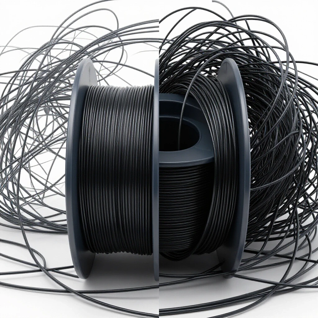
Early in my career, I spent three days chasing a feeding issue on a high-output mill. I replaced the gun, the liner, and the tips twice. I was convinced it was a motor fault. It turned out to be a spool hub tensioner that was tightened just an eighth of a turn too far, creating enough drag to overwhelm the drive rolls once the spool got lighter. That lesson stuck with me. In this guide, I’m going to walk you through the systematic diagnostic steps I use to keep wire moving consistently, ensuring your shop stays productive and your welds remain defect-free.
Establishing a Diagnostic Framework for Wire Delivery
A systematic approach to isolating mechanical friction and pressure variables within the wire path is the only way to avoid guesswork. When the wire fails to move at a constant rate, the temptation is to keep cranking down on the tension knob, but that often masks the real problem or creates a new one.
To start, I view the wire delivery system as a series of friction points. Every inch of travel from the spool to the contact tip introduces resistance. Our goal is to ensure that the drive rolls provide enough “push” to overcome that resistance without deforming the wire or causing it to buckle. I follow a “Path of Travel” audit, starting at the back of the machine and moving forward.
Identifying the Root Cause of Friction
Locating the specific point where resistance exceeds the driving force of the motor requires a process of elimination. If the wire is slipping, the friction is too high somewhere downstream. If the wire is tangling at the rolls, the blockage is severe.
I use a simple “Pull Test” to check the health of the system. I release the drive roll tension and try to pull the wire through the gun by hand from the nozzle end. If I have to strain, there is a mechanical bind. Building on this, I break the system down into three zones: the supply zone (spool and inlet), the drive zone (rolls and guides), and the delivery zone (liner and tip).
- Supply Zone: Check for spool “birdnesting” or overlapping wraps.
- Drive Zone: Inspect for worn grooves or improper tension settings.
- Delivery Zone: Look for kinking in the lead or a clogged contact tip.
Calibrating Drive Roll Pressure and Alignment
Adjusting the mechanical force applied to the wire ensures consistent movement without crushing the consumable. This is the most common area where fabricators make mistakes, often over-tightening the rolls and causing the wire to flake or “work-harden” before it even hits the liner.
In my experience, drive roll pressure should be the absolute minimum required to feed the wire steadily. If you can’t stop the wire by pinching it between your gloved fingers with moderate pressure, the tension is likely too high. High tension leads to “shaving,” where tiny bits of metal are scraped off the wire. These shavings eventually clog the liner, leading to the very slipping issues you were trying to fix.
Matching Groove Geometry to Wire Type
Selecting V-groove, U-groove, or knurled rolls based on the hardness and diameter of the consumable prevents slippage and wire deformation. Using the wrong roll is like trying to drive a car with the wrong size tires; it might move, but it won’t be efficient.
Interestingly, many intermediate fabricators use V-grooves for everything. However, if you are running soft wires like aluminum, a V-groove will pinch the wire into an oval shape, causing it to wedge inside the contact tip. Conversely, using a smooth U-groove for hard flux-cored wire won’t provide enough grip, leading to erratic feeding.
| Wire Type | Recommended Roll Groove | Why It Matters |
|---|---|---|
| Solid Carbon Steel | V-Groove | Provides a four-point grip on hard wire without slipping. |
| Aluminum / Soft Alloys | U-Groove | Cradles the wire to prevent crushing or “egging” the shape. |
| Cored Wires (Flux/Metal) | Knurled (V-K) | Bites into the tubular wire to provide grip without excessive pressure. |
Aligning the Inlet and Outlet Guides
Ensuring the guides are centered with the drive roll grooves prevents the wire from “climbing” out of the track and tangling. Even a misalignment of 0.010 inches can cause the wire to rub against the side of the guide, creating metal shavings and drag.
When I set up a feeder, I use a flashlight to look through the inlet guide. The wire should pass perfectly through the center of the rolls and into the outlet guide without touching the edges. If the wire is forced to “snake” through the drive assembly, you are adding unnecessary friction that the motor has to fight.
Managing the Internal Conduit and Liner Health
Maintaining the flexible tube that guides the wire from the feeder to the torch is critical to minimizing drag. The liner is essentially the “highway” for your wire, and if that highway is full of potholes or debris, your feed rate will never be consistent.
A common mistake is keeping a liner in service for too long. Over time, the internal diameter of the liner wears down, or it becomes packed with the shavings I mentioned earlier. I recommend blowing out the liner with compressed air every time you change a spool of wire. If you see a cloud of “dust” come out the end, you’ve just saved yourself a future feeding headache.
Trimming and Seating the Liner Correctly
Ensuring the liner is the precise length prevents gaps or buckling at the connection points where the wire can snag. This is the primary cause of the wire bunching up right after the drive rolls, a phenomenon often called “birdnesting.”
When installing a new liner, I always make sure it is seated firmly in the power pin. If the liner is cut too short, there will be a gap between the end of the liner and the gas diffuser. This gap allows the wire to flex and wander, which increases friction and leads to “micro-stuttering” in the arc. As a result, your weld quality suffers, and you might see increased spatter or porosity.
- Step 1: Lay the gun lead out completely straight on the floor.
- Step 2: Feed the liner in until it bottoms out against the head of the torch.
- Step 3: Mark the liner at the feeder end, then pull it back out slightly to cut it.
- Step 4: Use a file to remove any burrs from the cut end to prevent wire scratching.
Understanding Liner Materials and Friction
Different liner materials offer different coefficients of friction. For standard steel wire, a hardened steel coil liner is the industry standard. However, for stainless or aluminum, you might need a Teflon or Nylon liner to prevent “galling,” which is when the wire sticks to the liner material due to heat and friction.
| Liner Material | Best Use Case | Maintenance Tip |
|---|---|---|
| Steel Spiral | Solid/Cored Steel | Blow out with air every 44 lbs of wire. |
| Teflon / PTFE | Aluminum / Stainless | Replace if any kinks or “burn-back” occurs. |
| Brass / Copper | High-Heat Applications | Check for neck-to-liner alignment regularly. |
Optimizing Spool Tension and Braking
The spool hub assembly must provide just enough resistance to stop the spool from spinning once the trigger is released, without adding drag during the welding process. This is a delicate balance that many people overlook until they find a “nest” of loose wire inside their machine cabinet.
I calibrate spool tension by watching the wire when I stop a long weld. The spool should stop rotating almost instantly. If the spool continues to spin and the wire uncoils, the brake is too loose. If the drive rolls are struggling to pull the wire, or if you hear the motor “groaning,” the brake is too tight.
The “Gravity Test” for Spool Drag
A practical benchmark for spool tension is the “Gravity Test.” With the drive rolls disengaged, the weight of the wire should not be enough to turn the spool on its own. However, you should be able to turn the spool with one finger with very little effort.
In one case study I documented, a shop was experiencing “intermittent arc fluttering.” We traced it back to a spool of wire that was slightly out-of-round. Every time the “high spot” on the spool hit the tensioner, the drag increased, causing the wire speed to drop for a fraction of a second. By backing off the hub tension by just half a turn, the fluttering disappeared completely.
The Final Exit: Contact Tip and Torch Geometry
The contact tip is the final point of electrical and mechanical contact. If the tip is worn, oversized, or clogged with spatter, the wire will not feed smoothly, leading to “burn-back” where the wire fuses to the tip itself.
I always tell my team: the contact tip is a consumable, not a permanent fixture. If you’ve been welding for four hours straight, change the tip. It’s the cheapest insurance policy you have against feed issues. Furthermore, the angle of your torch neck can drastically affect internal drag. A “gooseneck” torch with a sharp 60-degree bend creates significantly more friction than a 45-degree or straight neck.
Troubleshooting Tip Wear and Heat Expansion
As the contact tip heats up, the hole in the center can actually expand or, if clogged with debris, contract and grip the wire. This is why you might start a shift with perfect feeding and end it with a stuttering arc.
- Check for “keyholing”: This is when the wire wears an oval shape into the tip. It causes the arc to wander and increases friction.
- Match tip size to wire: A .035 wire should use a .035 tip. Don’t try to run it through a .045 tip just because it’s all you have; you’ll get poor electrical contact and erratic feeding.
- Inspect the diffuser: Ensure the gas holes are clear and the tip is seated tightly. A loose tip creates heat buildup, which leads to wire expansion and sticking.
Systematic Diagnostic Checklist
When you encounter a feeding failure, don’t just start turning knobs. Use this numbered checklist to isolate the mechanical fault.
- Straighten the Lead: Ensure the torch cable is not coiled or kinked. A single loop in the lead can double the friction on the liner.
- Inspect the Spool: Look for “crossed” wire or a spool that has jumped the hub.
- Perform a Hand-Pull Test: Disengage rolls and pull wire through the tip. If it’s hard to pull, remove the tip and pull again. If it’s still hard, the problem is the liner.
- Check Drive Roll Alignment: Ensure the wire is sitting in the center of the groove.
- Test Tension: Use the “finger-pinch” method. If the rolls slip when you pinch the wire, tighten by half-turn increments until it stops slipping.
- Verify Tip Condition: Replace the contact tip with a fresh one of the correct size.
Case Study: The Mystery of the Buckling Wire
I once consulted for a shop that was losing two hours a day to “birdnesting” on their aluminum setup. They had replaced the drive rolls and the liners, but the wire kept tangling right at the outlet guide.
Upon inspection, I found they were using V-groove rolls on soft 4043 aluminum wire. The V-groove was crushing the wire into an oval shape. When that oval wire hit the round opening of the liner, it would wedge and stop. The drive rolls, still spinning, would then push the wire out the side, creating a massive tangle.
The fix was simple: – Swapped to U-groove rolls. – Reduced drive roll tension by 30%. – Installed a Nylon liner to reduce friction. – Result: Zero tangles for the rest of the week.
Actionable Benchmarks for Shop Maintenance
To keep your equipment running at peak performance, follow these mechanical tolerances and maintenance schedules.
- Liner Life: Replace every 150-200 lbs of solid wire, or every 50 lbs of flux-cored wire.
- Drive Roll Tension: Typically 2.5 to 3.5 on a 1-5 scale for most standard applications.
- Spool Drag: 3-5 lbs of force required to start rotation.
- Tip Tolerance: Replace if the orifice is more than 10% larger than the wire diameter.
Building on these metrics, I recommend keeping a “Maintenance Log” near each welding station. Tracking how often you change liners and tips can help you identify if a specific operator is over-tightening rolls or if a certain brand of wire is leaving more debris than others.
Conclusion and Next Steps
Mastering the mechanics of wire delivery is about respecting the physics of friction. By treating the wire path as a precision system rather than just a “hose,” you can eliminate 90% of common feeding issues. Start by auditing your current setup: check your roll types, blow out your liners, and calibrate your spool tension.
Your next step should be to perform the “Hand-Pull Test” on every machine in your shop. This will give you a baseline for what a “healthy” system feels like. Once you know what “smooth” feels like, you’ll be able to spot a problem before it ruins a weld.
Frequently Asked Questions
Why does my wire keep tangling at the drive rolls?
This is usually caused by a blockage or excessive friction downstream in the liner or contact tip. When the wire can’t move forward, the drive rolls keep pushing, causing the wire to buckle at the weakest point—usually the gap between the rolls and the liner inlet. Ensure your liner is trimmed correctly and your contact tip isn’t clogged.
How tight should the drive roll tension be?
The tension should be just enough to feed the wire without slipping. A good test is to pinch the wire between your fingers (with gloves on) while it’s feeding. If the rolls slip, tighten them slightly. If you can’t stop the wire at all, the tension is likely too high, which can lead to wire deformation and flaking.
Can I use the same drive rolls for all types of wire?
No. Hard wires like steel require V-grooves to grip the wire. Soft wires like aluminum require U-grooves to avoid crushing the wire. Cored wires require knurled rolls to “bite” into the outer sheath without collapsing the hollow center.
How often should I replace the liner?
For a professional shop, I recommend replacing the liner every 3 to 5 spools of wire. If you are using flux-cored wire, you may need to replace it more often due to the increased debris. Always blow the liner out with compressed air during every spool change.
What causes “shaving” or metal dust in the drive roll housing?
Shaving is caused by excessive drive roll pressure or misaligned guides. When the rolls are too tight, they scrape the surface of the wire. This dust then travels into the liner, creates friction, and eventually leads to feeding failures.
Why does the wire slip only after I’ve been welding for a while?
This is often due to heat expansion. As the contact tip and torch neck heat up, the friction inside the system increases. If your liner is dirty or your tip is worn, this extra heat is enough to “tip the scales” and cause the drive rolls to start slipping.
Is spool tension really that important?
Yes. If the spool brake is too loose, the wire will unspool and tangle inside the machine. If it’s too tight, the motor has to work harder to pull the wire, which leads to erratic feeding and premature wear on the drive rolls.
How do I know if my contact tip is the wrong size?
If the tip is too small, the wire will jam or feed with a “stutter.” If it’s too large, you will have poor electrical contact, leading to a “cold” arc and excessive spatter. Always match the tip size stamped on the side to the wire diameter you are using.
Does the length of the torch lead matter?
Absolutely. A longer lead (e.g., 15 feet vs 10 feet) has more internal surface area, which means more friction. If you are having constant feeding issues with a long lead, try to keep the lead as straight as possible during welding to minimize drag.
What is the best way to clean a liner?
Remove the wire from the gun, take off the contact tip, and use a compressed air nozzle at the feeder end to blow air through the liner. You should see a puff of dust exit the torch end. If the air doesn’t flow freely, the liner is kinked or completely clogged and must be replaced.
(This article was written by one of our staff writers, Paul Whitaker. Visit our Meet the Team page to learn more about the author and their expertise.)