How to Align and Adjust Belt Grinder Pulleys (DIY Guide)
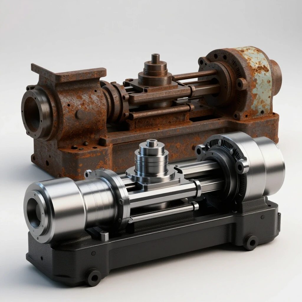
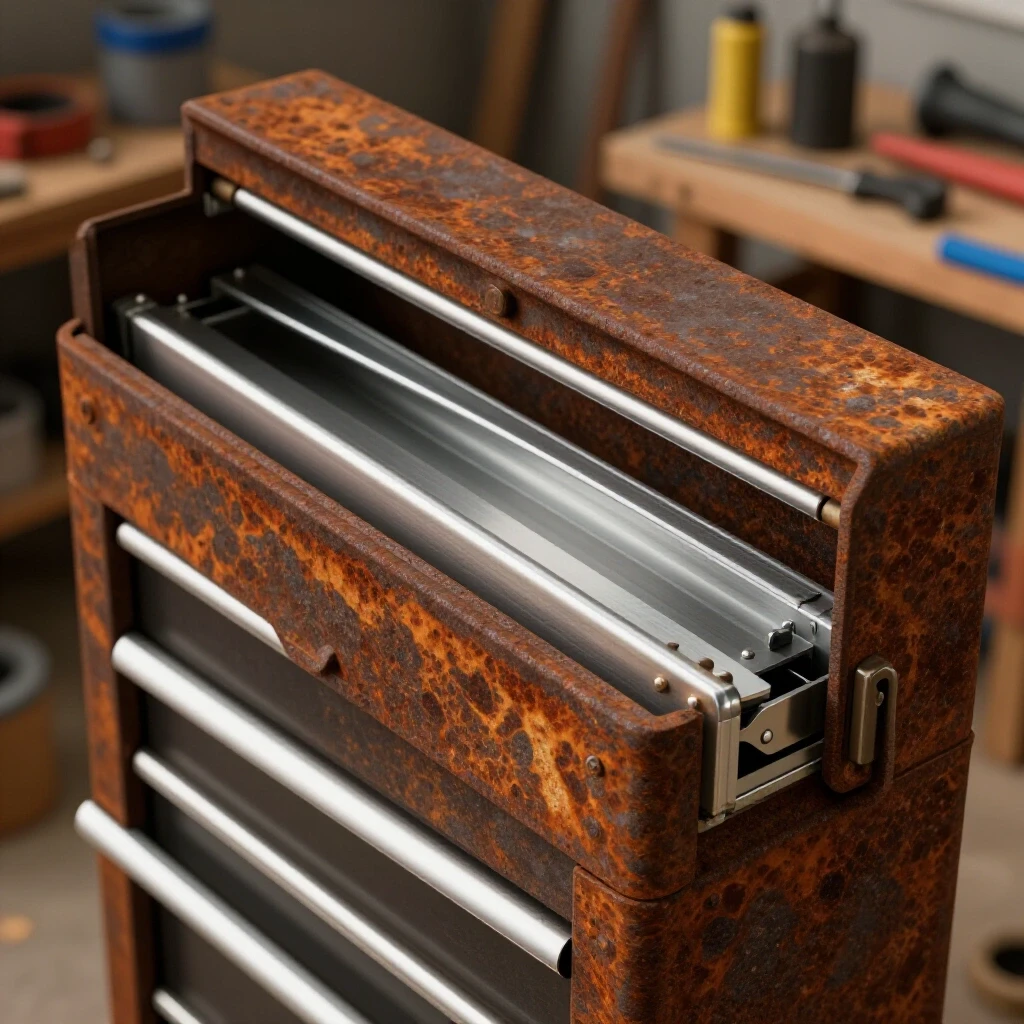
The first time I hauled a rusted, pre-war abrasive belt machine into my shop, I spent three days just staring at the seized tracking mechanism. It was a heavy, cast-iron beast from an era when tools were built to last a century, but decades of neglect in a damp basement had fused the components into a single orange block of oxidation. Restoring these machines isn’t just about making them look good; it is about reclaiming the mechanical precision that allows a high-speed abrasive belt to run true without flying off the wheels.
In my 18 years of reviving neglected workshop equipment, I have learned that the heart of any belt-driven tool lies in its geometry. If the wheels are not co-planar, or if the tracking hinge has even a fraction of an inch of slop, the machine becomes a vibration-heavy liability rather than a precision tool. Successful restoration requires a blend of chemical patience, mechanical forensics, and a steady hand with a straightedge.
Evaluating the Structural Integrity of Vintage Abrasive Machines
Before turning a single wrench, you must determine if the heavy castings and structural members are sound enough to support the tension of a modern abrasive belt. This phase involves a deep cleaning to reveal hidden cracks in the cast iron and an assessment of the frame’s squareness, which dictates how well the wheels will eventually line up.
Cast iron is a wonderful material for dampening vibration, but it is brittle and prone to “stress-creeping” over decades if stored under uneven loads. I start by stripping the heaviest grease with a plastic scraper to inspect the main uprights and the tracking arm pivot. If I find a hairline crack, I have to decide if a nickel-rod weld or a braze repair is feasible, or if the part must be fabricated from scratch.
- Visual Inspection: Look for “spiderwebbing” in the paint, which often indicates localized stress or impact damage.
- The Ring Test: Lightly tap large castings with a small brass hammer; a clear ring suggests solid metal, while a dull thud often points to a hidden internal crack.
- Frame Squareness: Use a machinist’s square to check the relationship between the base and the vertical tracking column.
| Feature | Healthy State | Warning Sign |
|---|---|---|
| Pivot Points | Smooth, circular bores | Oval-shaped or “egged” holes |
| Casting Surface | Uniform texture under rust | Pitting deeper than 1/16th inch |
| Alignment Surfaces | Flat and parallel | Twisted or warped from heat |
Strategies for Disassembling Seized Tracking Mechanisms
Obsolete technical documentation often makes disassembly a guessing game, especially when dealing with hidden set screws or tapered pins that have been painted over multiple times. When a tracking hinge or a pulley shaft refuses to budge, applying brute force is the fastest way to crack a piece of history that cannot be replaced.
I rely on a “soak and heat” cycle that respects the metallurgy of the tool. I begin with a 50/50 mix of automatic transmission fluid and acetone, which I find penetrates tighter tolerances than most commercial sprays. If the part remains stuck after 48 hours, I introduce localized heat. The goal is to expand the outer casting slightly faster than the inner steel shaft, breaking the bond of the rust.
- Clear the Paint: Use a wire brush to find every hidden fastener; many old machines use “dog-point” set screws hidden under layers of grime.
- Chemical Penetration: Apply your chosen oil every few hours, tapping the casting lightly with a dead-blow hammer to create vibrations that help the fluid “wick” into the threads.
- Thermal Expansion: Use an oxy-acetylene torch with a rosebud tip to heat the casting to about 400 degrees Fahrenheit—enough to expand the metal but not enough to change its temper.
- Mechanical Advantage: Use a puller rather than a hammer whenever possible to apply steady, even pressure to shafts and pulleys.
Removing Heavy Corrosion Without Damaging Base Metal
Removing machinery rust is a delicate balance between efficiency and preservation; you want to kill the oxidation without “pitting” the precision-ground surfaces where the pulleys sit. For large, complex castings like the tracking arms or platen supports, I prefer chemical baths over aggressive grinding, as they preserve the original machining marks and “witness lines.”
I often use an electrolysis bath for the most stubborn pieces. By submerged the part in a solution of washing soda and water and applying a 12V DC current, the rust is converted and lifted away from the healthy metal. This process is non-destructive and reaches into the deep recesses of a tracking hinge where a wire wheel cannot go. For smaller, more delicate parts, a modern water-based chelator is safer and requires less monitoring.
- Electrolysis Setup: Use a sacrificial steel anode and a manual battery charger; avoid “smart” chargers as they often shut off when they don’t detect a battery.
- Chelating Agents: These solutions (like Evapo-Rust) work by bonding to the iron oxide molecules specifically, leaving the base steel untouched.
- Wire Brushing: Only use brass or fine steel wheels on a bench grinder for non-critical surfaces to avoid “rounding over” sharp edges needed for alignment.
Synchronizing Drive and Tracking Wheel Geometry
Once the parts are clean and the shafts move freely, the real work of perfecting the belt path begins. In a belt-driven system, the drive wheel and the idler (or tracking) wheel must be perfectly co-planar, meaning they exist in the same two-dimensional plane when viewed from the side. If one wheel is tilted or offset even by 0.050 inches, the belt will constantly fight to “climb” off the edge.
I use a long, precision-ground straightedge to bridge the gap between the wheels. By holding the straightedge against the face of the drive wheel, I can see exactly how the tracking wheel sits in relation to it. I look for two types of misalignment: “offset,” where the wheels are parallel but not lined up, and “angular,” where one wheel is tilted relative to the other.
- Axial Alignment: Shimming the pulleys on their respective shafts to ensure the centerlines of the wheels are perfectly matched.
- Vertical Plumb: Using a machinist’s level to ensure the shafts are horizontal and the vertical supports haven’t sagged over time.
- Tracking Range: Ensuring the tracking hinge has enough travel to tilt the wheel both forward and backward, allowing the belt to be steered to the center.
Understanding the Role of Wheel Crowning in Tracking
A common mistake I see in DIY restorations is the attempt to make every wheel perfectly flat. In reality, a belt grinder usually requires at least one “crowned” wheel—usually the tracking idler—to keep the belt centered. Crowning is a slight taper where the center of the wheel has a larger diameter than the edges, creating a “hump.”
The physics here are fascinating: a flexible belt will always try to climb to the highest point of a rotating cylinder. By having a crown of about 1 to 2 degrees on the tracking wheel, the belt is naturally pulled toward the center. If your vintage machine has a flat tracking wheel that has worn down over the years, you may need to “re-crown” it on a lathe to restore its ability to steer the belt reliably.
| Crown Angle | Effect on Tracking | Best Use Case |
|---|---|---|
| 0 Degrees (Flat) | Very aggressive, prone to wandering | Contact wheels for flat grinding |
| 1 Degree Taper | Subtle, stable centering | High-speed 2×72 industrial setups |
| 2-3 Degree Taper | Strong centering force | Narrow belts or worn tracking hinges |
Servicing Legacy Bearings and Rebuilding Sleeve Housings
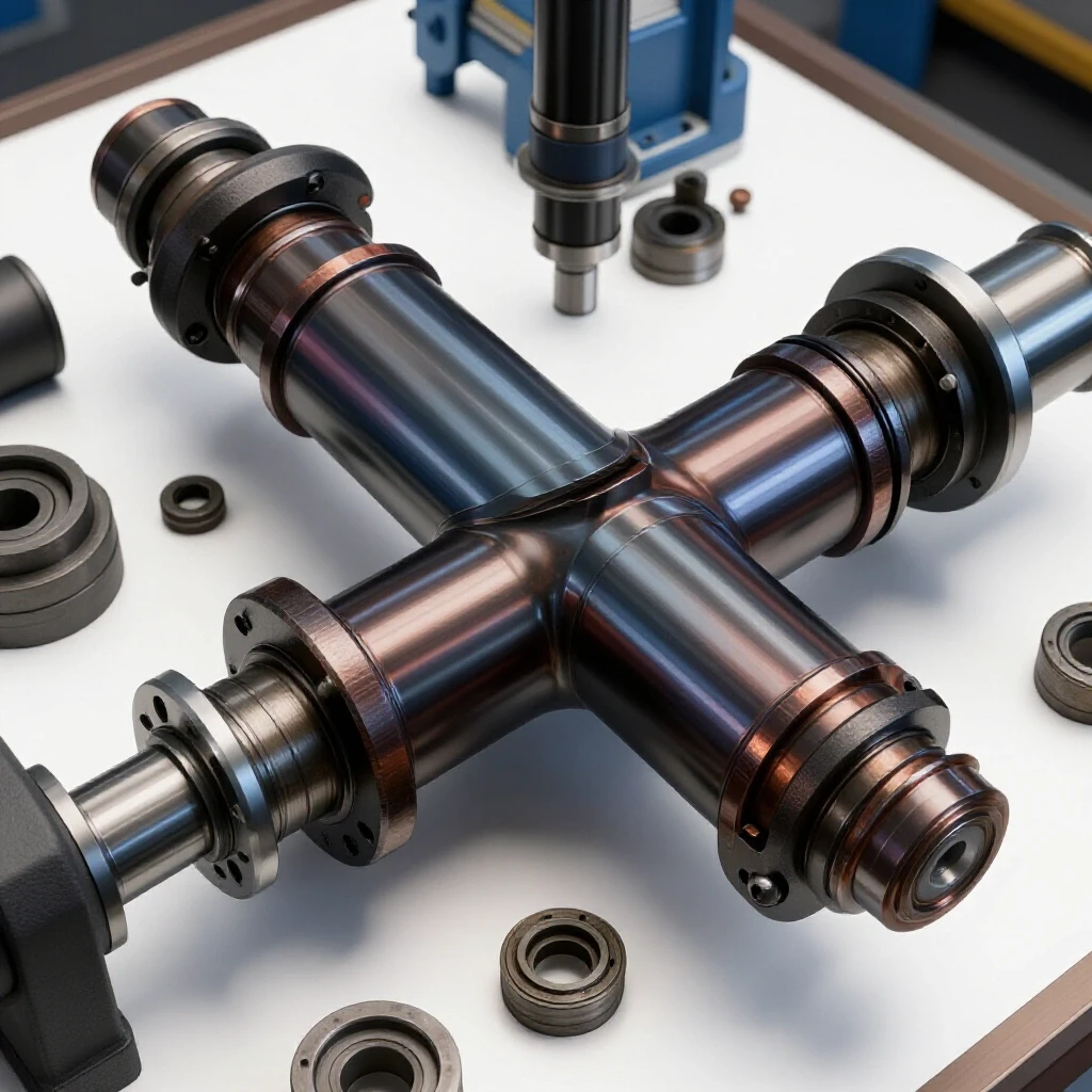
Many pre-war machines do not use modern sealed ball bearings; instead, they rely on babbitt or bronze sleeve bearings. These require a specific clearance—usually between 0.001 and 0.002 inches—to allow a thin film of oil to support the shaft. If these bearings are worn, the pulley will wobble, causing the belt to vibrate and track inconsistently.
If I find excessive “slop” in a sleeve bearing, I have to decide whether to bore it out for a modern needle bearing or to pour new babbitt. Pouring babbitt is a lost art that involves melting a lead-tin alloy and casting it directly around the shaft. It is a messy, hot process, but it preserves the historical integrity of the machine and provides a bearing surface that can last another fifty years if properly lubricated.
- Measure Clearance: Use a dial indicator to check for radial play in the pulley shafts.
- Check for Scoring: Inspect the shaft for deep grooves; a scored shaft will shred a new bearing in minutes.
- Lubrication Paths: Ensure the oil cups or “wicking” systems are clear of old, solidified grease that blocks fresh oil from reaching the friction surfaces.
Calibrating the Tracking Hinge for Precision Steering
The tracking hinge is the most critical mechanical assembly for belt stability. It must be stiff enough to hold its position under the high tension of a ceramic belt, yet smooth enough to allow for micro-adjustments while the machine is running. In many old tool rescues, I find that the pivot pin for this hinge is badly worn, leading to a “floppy” tracking wheel.
I often have to fabricate an oversized pivot pin and re-ream the holes in the tracking arm to restore a snug fit. A tight hinge ensures that when you turn the tracking knob, the wheel moves in a pure arc without any side-to-side “lash.” This precision is what separates a tool that is frustrating to use from one that feels like a professional instrument.
- Tension Spring Selection: Replace old, fatigued springs with ones that provide a consistent 20-30 lbs of force to keep the tracking mechanism loaded.
- Thread Restoration: If the tracking adjustment bolt is a non-standard vintage pitch, I use a thread chaser rather than a die to preserve as much original metal as possible.
- Friction Dampening: Sometimes adding a nylon washer to the pivot can provide just enough resistance to prevent the tracking from “drifting” due to machine vibration.
Final Alignment Testing and Vibration Analysis
After the rust is gone, the bearings are snug, and the wheels are co-planar, it is time for the “dry run.” I start by rotating the wheels by hand with a belt installed. I watch how the belt reacts to the tracking knob. It should move smoothly across the face of the wheels with no jumping or sudden lurches.
Once I am satisfied with the manual tracking, I power the system at its lowest speed. I use my fingertips (carefully) to feel for vibrations in the frame. High-frequency vibration usually points to an out-of-balance wheel or a bent shaft, while a low-frequency “thumping” often means the belt splice is too thick or the wheels are significantly out of round.
- The “Hand-Spin” Test: Ensure the belt stays centered for at least ten full rotations by hand.
- Wheel Runout Check: Use a dial indicator on the face and edge of each pulley; runout should ideally be less than 0.003 inches.
- Heat Check: After five minutes of operation, feel the bearing housings. They should be warm to the touch, but never hot enough to be uncomfortable.
Frequently Asked Questions
Why does my belt always track to the left, no matter how I adjust the knob? This is usually caused by the drive wheel and the idler wheel being “out of plane” or non-parallel. Even if the tracking wheel tilts, if the drive wheel is offset to the side, the belt will always try to find a path that minimizes tension, which usually results in it running off the edge. Use a straightedge to ensure the wheels are perfectly lined up axially.
Can I use a flat wheel for tracking if I don’t have a crowned one? You can, but it will be incredibly difficult. A flat wheel has no “preference” for where the belt sits. Without a crown, the slightest imperfection in the belt or a tiny bit of grit on the wheel will cause the belt to wander. You can create a temporary crown by wrapping a few layers of electrical tape around the center of a flat idler wheel to see if it improves tracking.
How do I know if my vintage cast-iron pulleys are too worn to use? Look for “cupping” or a hollowed-out center on the face of the pulley. If the center is lower than the edges, the belt will never track properly because it’s fighting the “reverse crown.” If you have more than 0.010 inches of wear across the face, the wheel needs to be turned flat on a lathe and then properly re-crowned.
What is the best way to clean old grease out of internal oil galleys? Old mineral-based greases turn into a waxy solid over time. I find that a combination of heat (from a heat gun) and a pressurized solvent like brake cleaner works best. For very stubborn blockages, I use a small bit of stiff copper wire to mechanically poke through the blockage.
Is it safe to use a wire wheel on the bearing surfaces of the shafts? I strongly advise against it. A wire wheel can remove metal and create an uneven surface, which will ruin the tight tolerances needed for a sleeve bearing. Use a fine Scotch-Brite pad or 600-grit sandpaper backed by a flat block of wood to gently “polish” the rust off a shaft without changing its diameter.
How much tension should a belt grinder have? A general rule of thumb for 2-inch wide belts is enough tension so that you can only deflect the belt about 1/2 inch with firm thumb pressure in the center of its longest span. Too much tension will cause the bearings to overheat and can even bend the tracking arm on older, lighter-duty machines.
My tracking adjustment knob is very hard to turn under tension. Why? This is often due to “galling” in the threads or a lack of lubrication on the point where the adjustment bolt contacts the tracking arm. Clean the threads thoroughly and apply a small dab of high-pressure grease or anti-seize to the tip of the bolt.
What should I do if the original fasteners are an obsolete thread pattern? If the threads are stripped and you can’t find a replacement, your best bet is to plug the hole with a threaded steel insert or a “Keensert.” This allows you to use a modern, readily available bolt while maintaining the structural integrity of the original casting.
How do I check if my pulleys are out of balance? Remove the belt and spin the pulley by hand. If it always stops with the same side facing down, it is “statically” out of balance. You can drill small amounts of metal out of the “heavy” side on the underside of the rim to balance it, much like a car tire.
Can I replace babbitt bearings with modern ball bearings? It is possible, but it usually requires machining the original casting to accept the larger outer diameter of a ball bearing. This can weaken the casting. Often, it is better to simply pour new babbitt or press in a new bronze sleeve, which preserves the original design and provides excellent vibration dampening.
Why does my belt vibrate more at higher speeds? Vibration that increases with speed is almost always due to “dynamic imbalance” in the wheels or a belt that has a poor-quality lap joint. Try a different belt first; if the vibration persists, the wheels likely need to be balanced or trued on a lathe to ensure they are perfectly concentric with the shaft.
What is the most common mistake in belt machine restoration? The most common mistake is rushing the disassembly and cracking a casting. People lose patience with a stuck bolt and reach for a bigger hammer. In the world of vintage machinery, time is your best tool. If a part is stuck, let it soak for another week. The machine has been around for 80 years; it can wait seven more days for you to do it right.
(This article was written by one of our staff writers, Richard Beaumont. Visit our Meet the Team page to learn more about the author and their expertise.)