How to Align and Square a Drill Press Table (DIY Guide)
In my fourteen years of inspecting structural steel and managing shop floors, I have learned that the smallest geometric error can lead to the most frustrating project failures. I remember a specific job where we were building a heavy-duty engine hoist frame. We had prepped the square tubing perfectly and our welds looked like stacked dimes. However, when it came time to bolt the main pivot assembly together, nothing lined up. The bolts were going in at an angle, binding against the steel walls. We discovered that the holes, drilled on a standard floor-standing drill press, were slightly skewed. That 1.5-degree error at the table translated into a structural nightmare that required us to grind out welds and start over.
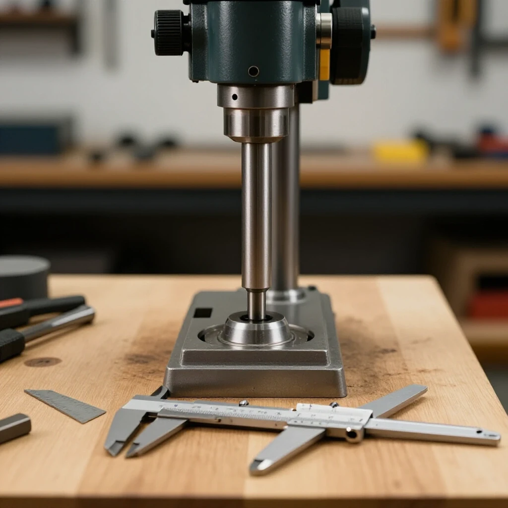
This experience taught me that a drill press is only as good as its relationship to the work surface. If the spindle axis and the table are not perfectly perpendicular, every hole you drill becomes a potential point of failure. In structural fabrication, an angled hole creates uneven loading on fasteners. Instead of a bolt sitting flush and distributing tension across its entire flange, it bites into one edge. This creates a localized stress riser that can lead to brittle fracture or fatigue failure under load. Ensuring your machine is properly calibrated is not just about making parts fit; it is about the structural integrity and safety of your final build.
The Physics of Perpendicularity in Hole Production
The core goal of machine calibration is to ensure the spindle—the part that rotates the drill bit—is exactly 90 degrees to the table in every direction. This geometric relationship is often called being “square” or “in tram.” When these two components are out of alignment, the drill bit enters the material at an angle, which causes the bit to “walk” or deflect as it bites into the metal.
In metalworking, even a minor deviation can cause significant issues. For example, if you are drilling through a 2-inch thick steel block and your table is off by just one degree, the exit hole will be nearly 0.035 inches away from where it should be. This might not sound like much, but in a precision assembly, it is the difference between a bolt sliding in by hand and having to use a sledgehammer. More importantly, it creates a “shear path” that was not intended in your structural design, potentially compromising the structural metal load capacity of the joint.
Table 1: Impact of Angular Error on Hole Displacement
| Angle of Error (Degrees) | Displacement at 1″ Depth | Displacement at 3″ Depth | Structural Risk Level |
|---|---|---|---|
| 0.5° | 0.0087″ | 0.0261″ | Low – Cosmetic |
| 1.0° | 0.0175″ | 0.0524″ | Moderate – Fitment Issues |
| 2.0° | 0.0349″ | 0.1047″ | High – Fastener Binding |
| 3.0° | 0.0524″ | 0.1572″ | Critical – Structural Failure |
Essential Workshop Safety Checklist for Machine Calibration
Before you begin adjusting heavy iron components, you must establish a safe working environment. Maintenance and calibration are when many “near-miss” incidents occur because guards are often removed and hands are placed near pinch points. I always follow a strict protocol to ensure that the machine cannot accidentally energize while I am measuring or adjusting.
- Power Isolation: Unplug the machine from the wall. Do not rely on the “off” switch alone.
- Table Stability: Ensure the table locking handle is functional. A heavy cast-iron table can drop suddenly if the rack-and-pinion system is worn.
- Debris Removal: Use a wire brush and a stone to remove any burrs or dried coolant from the table surface. A single metal chip measuring 0.005 inches under your square will ruin your entire calibration.
- Lighting: Use a high-intensity work light to see the “daylight” between your square and the drill bit.
- Tool Inspection: Verify that your machinist square is not bent and that your dial indicator moves freely without sticking.
Measuring Geometric Errors with Precision Tools
To fix a problem, you first have to quantify it. I start by using a high-quality machinist square. This is a steel tool ground to a very tight tolerance, usually within 0.0001 inches per inch. Place the square on the table and bring the spindle down so a clean, straight drill blank or a piece of precision ground rod is held in the chuck.
Look for light passing between the square and the rod. If you see more light at the top than the bottom, the table is tilted away from the column. If you see more light at the bottom, it is tilted toward it. This “daylight test” is a quick way to find gross errors. For more precise work, I use feeler gauges—thin strips of metal with known thicknesses—to fill the gap between the square and the rod. This tells me exactly how many thousandths of an inch I am out of square.
Common Measurement Pitfalls
- Chuck Runout: If your chuck is cheap or damaged, the rod itself might be spinning in an oval. Always rotate the spindle by hand to see if the gap changes.
- Table Sag: On some budget drill presses, the weight of the square or your hand can flex the table. Always measure with minimal pressure.
- Column Flex: Pushing against the machine while measuring can temporarily “fix” the error, giving you a false reading.
Correcting Table Tilt and Column Misalignment
Most drill presses have a pivoting table that allows you to tilt it for angled holes. This pivot point is usually secured by a large bolt and sometimes a “zero-point” pin. Over time, these pins can become loose or the bolt can vibrate partially open, leading to “mechanical drift.”
To correct the side-to-side tilt, loosen the main pivot bolt just enough so the table can move with a firm tap from a rubber mallet. Do not loosen it so much that the table flops around. Adjust the table until your square shows no daylight against the rod in the chuck. Once you think it is perfect, tighten the bolt in stages. Tightening a bolt often pulls the metal slightly, so re-check your squareness after every quarter-turn.
If the table is out of square from front-to-back (tilting toward or away from the column), the fix is more complex because most hobbyist machines do not have a built-in adjustment for this. This usually indicates that the “bore” of the table bracket or the column itself is slightly off. In these cases, we must use shimming techniques to bring the geometry back into spec.
Advanced Verification Using Dial Indicators
When I am working on structural components where hole alignment is critical for safety, I move beyond the machinist square and use a dial indicator. A dial indicator is a tool that measures small distances (usually in increments of 0.001 inches) via a needle on a circular face. By “sweeping” the table with an indicator, you can find errors that a square would never show.
To do this, I create a simple “tramming tool.” This is often just a piece of stiff steel rod bent into an “L” shape. One end goes into the drill chuck, and the other end holds the dial indicator. As you rotate the spindle by hand, the indicator travels in a wide circle around the table. If the needle stays at zero as it moves 360 degrees, your spindle is perfectly perpendicular to the table. If the needle moves, it shows you exactly where the table is “low” or “high.”
Table 2: Dial Indicator Sweep Diagnostic
| Indicator Reading (High Spot) | Probable Cause | Corrective Action |
|---|---|---|
| Left or Right side | Table pivot is not set to 0° | Loosen pivot bolt and re-align |
| Front (Near operator) | Table bracket is sagging | Shim the table-to-bracket interface |
| Back (Near column) | Column is leaning forward | Shim the base of the column |
| Random/Inconsistent | Spindle bearings are worn | Replace spindle bearings |
Shimming for Permanent Structural Accuracy
Shimming is the process of inserting very thin pieces of material—usually brass, steel, or even aluminum from a soda can—between two components to change their alignment. In my years of fabrication, I have found that shimming is often the only way to fix a factory defect in a machine’s casting.
If your drill press table tilts forward, you can place a small shim between the table’s mounting bracket and the table itself. This lifts the front edge. I prefer using brass shim stock because it does not compress easily and resists corrosion. Start with a 0.002-inch shim and re-test with your dial indicator. It is a process of trial and error, but it results in a machine that produces holes as accurate as a high-end milling machine.
Why Shimming Matters for Joint Integrity
When your table is square, the “heat affected zone” (HAZ) created during subsequent welding stays uniform. If a hole is drilled at an angle, the wall thickness of the metal surrounding the hole varies. When you weld near that hole, the thinner section of metal will reach its melting point faster, leading to potential burn-through or a weakened structural joint. Maintaining a square table ensures that your material thickness remains consistent, which makes your welding gas flow rate and heat settings more predictable.
Case Study: The Failed Bracket and the 2-Degree Error
I once worked on a project involving a heavy-duty gate hinge. The hinge pins were 1-inch thick hardened steel, meant to be pressed into holes drilled through 1/2-inch plate. The fabricator didn’t bother to check if his drill press was square. He assumed the “factory zero” pin was accurate.
As he drilled the holes, the bit exited the bottom of the plate about 0.020 inches off-center. When he tried to press the pins in, they went in crooked. Because the pins were not perpendicular to the hinge plates, the gate would bind every time it moved. The lateral force on the hinges was so high that the welds began to show signs of stress cracking within a week. We had to cut the hinges off, re-drill the holes on a calibrated machine, and use a larger pin. This mistake cost three days of labor and $400 in wasted materials. The root cause was a table that was only 2 degrees out of square.
Troubleshooting Common Drill Press Deflections
Even a perfectly squared table can fail you if the machine flexes under load. This is a common issue in garage fabrication where we might be using a lighter-duty press to drill large holes in thick plate.
- Table Flex: If you apply 50 pounds of downward pressure on a drill handle, the table can flex downward. To prevent this, I often use a “table jack”—a simple screw jack placed between the floor (or the machine base) and the underside of the table.
- Spindle Runout: This is “wobble” in the spindle itself. You can check this by placing your dial indicator against the side of a smooth rod in the chuck and spinning it. If it moves more than 0.005 inches, your holes will always be oversized.
- Quill Slop: If the spindle can move side-to-side inside the head of the press, your alignment will change as soon as the bit touches the metal. Some machines have a pinch bolt on the head to tighten this up.
Actionable Framework for Machine Verification
To maintain a high standard of safety and quality, I recommend a monthly “accuracy audit” for your drill press. This ensures that vibration and heavy use haven’t knocked your machine out of alignment.
- Clean: Remove all oil and chips from the table and spindle.
- Rough Check: Use a machinist square to verify the 90-degree relationship on two axes (X and Y).
- Fine Check: Perform a dial indicator sweep. Aim for a total deviation of less than 0.003 inches over a 6-inch circle.
- Fastener Torque: Check the tightness of the table pivot bolt and the column mounting bolts.
- Lubrication: Apply a light coat of oil to the column and rack to prevent rust, which can pit the metal and cause the table to sit unevenly.
By following these steps, you reduce the risk of “welding defect troubleshooting” later in the project. Most fit-up issues in welding are actually machining issues in disguise. When your holes are square, your parts fit better, your welds are stronger, and your structures are safer.
FAQ: Ensuring Precision in Your Workshop
How often should I check the squareness of my machine? I check mine before every major structural project. For general hobby use, a quick check with a machinist square once a month is usually enough to catch any “drift” caused by vibration.
Can I use a standard carpenter’s square for this? No. Carpenter’s squares are designed for wood and have much wider tolerances. For metalwork, you need a machinist square (Grade B or better) to ensure the accuracy required for structural metal load capacity.
What is the best material for shimming a table? Brass or stainless steel shim stock is best. Avoid using paper or plastic, as these can compress or degrade over time, causing your table to become un-square again during a heavy cut.
Does spindle speed affect alignment? While speed doesn’t change the physical alignment, high speeds on an un-square table increase friction and heat. This can lead to “work hardening” of the material, making it harder to drill and increasing the risk of bit breakage.
My table has a “zero” notch, isn’t that enough? In my experience, factory “zero” marks are often off by 1 or 2 degrees. They are fine for rough construction but should never be trusted for precision structural work or when building heavy frames.
What do I do if my column is crooked? If the column is not perpendicular to the base, you can shim between the column flange and the base casting. This is rare but common on very cheap or very old, abused machines.
How does an un-square hole affect bolt strength? When a bolt is tightened into a crooked hole, the head of the bolt only touches on one side. This creates a “bending moment” on the bolt shank, which can cause the bolt to snap at a much lower tension than its rated PSI yield strength.
Can I align the table using a drill bit? I don’t recommend it. Drill bits are not perfectly straight and the flutes make it hard to get a good reading with a square. Always use a precision ground rod or a “drill blank.”
What is “tramming”? Tramming is the specific process of using a dial indicator to ensure the spindle axis is perfectly perpendicular to the table surface. It is the gold standard for machine alignment.
Is it safe to use a drill press with significant spindle runout? Significant runout (over 0.010 inches) makes the machine vibrate and can cause bits to shatter. It also makes it impossible to drill an accurate hole, which compromises the safety of any structural joint you are trying to create.
(This article was written by one of our staff writers, James Harlan. Visit our Meet the Team page to learn more about the author and their expertise.)