How to Calculate Optimal Batch Runs for Small Shops (DIY Fix)
For more than two decades, I have lived the evolution of a fabrication shop from the inside out. It started with a manual mill and a stick welder in a corner of a garage, but it eventually grew into a streamlined operation driven by CNC technology and lean principles. The transition from a hobbyist mindset to a professional production flow is rarely about buying the biggest machine. Instead, it is about how you manage the space, power, and time you already have. When you start scaling, you quickly realize that the biggest enemy isn’t a lack of skill; it is the friction of your own workflow.
Scaling a home-based or light commercial shop brings a unique set of stresses. You are often the lead engineer, the janitor, and the accountant all at once. As orders increase, the bottlenecks that were once minor annoyances—like moving a heavy sheet of steel across the room or waiting for a compressor to catch up—become major production killers. This guide focuses on the strategic redesign of your shop to handle higher volumes through smarter layout planning, electrical upgrades, and a systematic approach to deciding how many parts to run at once.
Analyzing Material Movement and Floor Layout
A shop layout defines how efficiently raw materials transform into finished products by mapping the physical path of every component to minimize wasted movement.
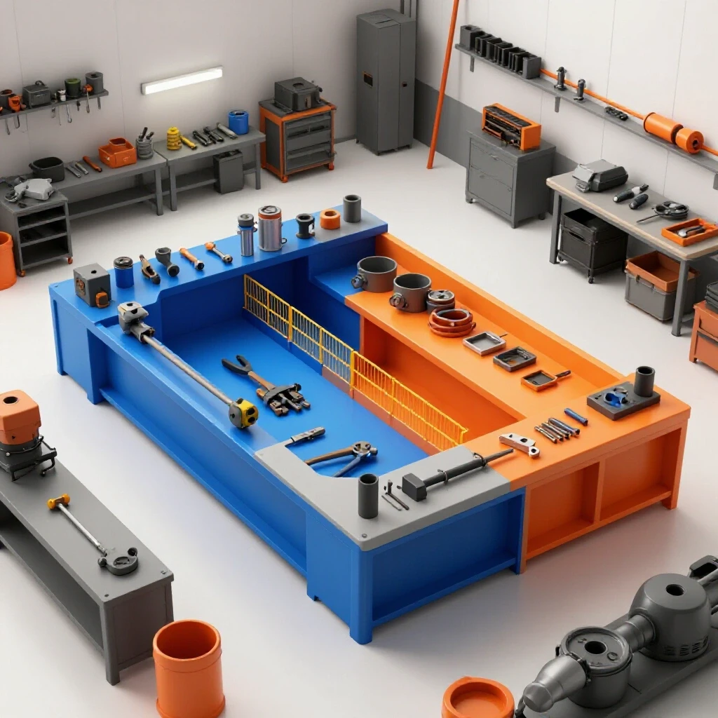
In my early years, I spent half my day just moving things out of the way to get to other things. This is the “hidden tax” of a poorly planned shop. To fix this, you must view your floor as a manufacturing cell. The goal is a linear or U-shaped flow where material enters at one point and exits at another without ever doubling back.
Defining Machine Zoning and Access Boundaries
Machine zoning involves grouping equipment by function and ensuring every tool has a dedicated “operator envelope” that allows for safe movement and maintenance access.
I recommend a minimum of a 3-foot access zone around every major piece of equipment. For a CNC plasma table, this zone needs to be even larger on the loading side to accommodate a forklift or gantry crane. When I integrated my first 4×8 plasma table, I didn’t account for the “swing room” of the metal sheets. I ended up having to move a heavy welding bench because I couldn’t load the table without hitting it.
- Primary Work Zone: High-traffic areas like welding tables and CNC consoles.
- Material Buffer: Space designated for raw stock near the start of the production line.
- Tooling Stations: Small footprints for grinders, clamps, and consumables located within arm’s reach of the work zone.
Evaluating Floor Load Ratings for Heavy Machinery
Floor load rating is the measure of how much weight your concrete slab can support per square foot without cracking or shifting under the vibration of heavy equipment.
Standard residential garage slabs are often 4 inches thick, rated for roughly 3,000 to 3,500 PSI. While this is fine for a car, a heavy CNC mill or a fully loaded sheet rack can create “point loads” that exceed these limits. When I installed my vertical machining center, I had to verify the slab thickness. If you are moving into high-volume production, consider anchoring heavy machines with epoxy studs to dampen vibration, which improves part accuracy and tool life.
| Layout Type | Flow Efficiency | Space Utilization | Best For |
|---|---|---|---|
| Linear Flow | High | Moderate | Long, narrow shops |
| U-Shaped Flow | Very High | Excellent | Square or compact shops |
| Functional Cell | Moderate | High | Varied, low-volume jobs |
| Island Layout | Low | Poor | Massive, oversized workpieces |
Determining Production Quantities for Maximum Efficiency
Calculating the ideal number of parts to produce in one session involves balancing the time spent setting up a machine against the time it takes to actually cut or weld each unit.
Every time you change a tool, load a new program, or adjust a jig, you are in “setup mode.” You aren’t making money during setup. The goal is to spread that setup cost over as many parts as possible without creating a storage nightmare. I use a simple ratio: if my setup takes 60 minutes, I want my total run time to be at least four to five times that duration. This ensures that the overhead of getting the machine ready doesn’t swallow the profit of the job.
Balancing Setup Overhead with Run Time
Setup overhead is the non-productive time required to prepare a machine for a specific task, including cleaning, tool offsets, and material loading.
In a small shop, we often fall into the trap of making “just one” of something. If you have to set up a CNC plasma table, home the gantry, and load a partial sheet just for one bracket, your effective hourly rate plummets. I’ve learned to group similar jobs. If I have three different customers needing 10-gauge steel parts, I run them all in one “batch” to minimize the number of times I have to clear the table and swap material.
Managing Material Yield and Nesting Logic
Nesting logic is the process of arranging parts on a raw sheet of material to minimize scrap and maximize the number of finished goods per square foot.
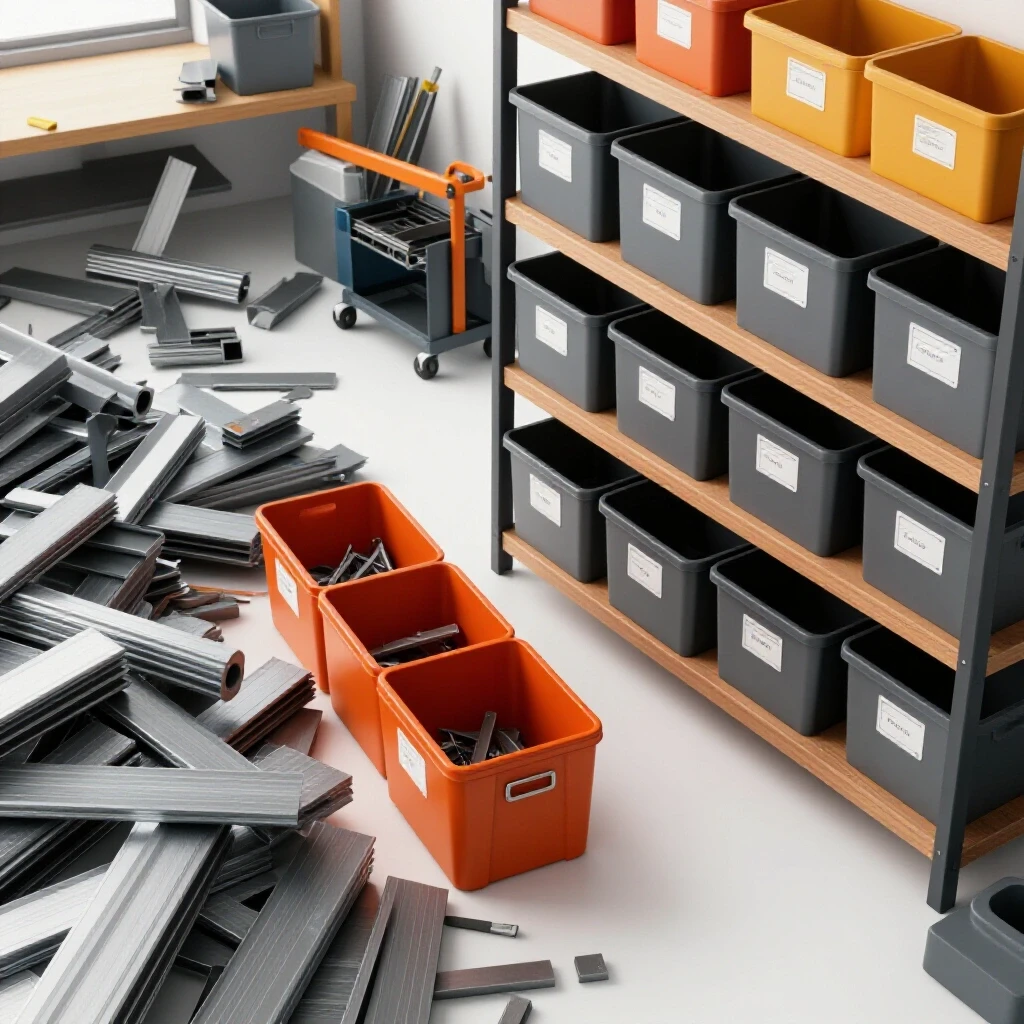
Modern CAD/CAM software helps with this, but it requires a human eye for “remnant management.” When I run a production cycle, I look at the skeleton—the leftover web of metal. If I can fit small “filler parts” like gussets or tabs into the gaps of a larger job, I am essentially getting those parts for free. This reduces my scrap rate and improves the overall value of the production run.
- Common Line Cutting: Sharing a single cut path between two parts to save time and gas.
- Lead-in Optimization: Placing entry points in scrap areas to prevent marring the finished edge.
- Bridge Cutting: Keeping parts connected to the skeleton to prevent “tip-ups” that can crash the CNC head.
Building Balanced 3-Phase Power Systems
A 3-phase power system provides a more consistent and efficient delivery of electricity for industrial motors, often requiring a converter in residential or light commercial settings.
Most home-based shops are limited to 240V single-phase power. However, professional-grade mills, lathes, and large compressors often run on 3-phase power. To bridge this gap, I’ve relied on Rotary Phase Converters (RPC). An RPC uses a “idler motor” to generate a third leg of electricity. It is a robust, mechanical solution that handles the high inrush current of starting a heavy motor much better than cheap static converters.
Comparing Rotary and Digital Phase Converters
Rotary converters use mechanical rotation to create the third phase, while digital or “solid-state” converters use power electronics to synthesize a clean 3-phase signal.
Digital converters are incredibly efficient and provide “perfect” 120-degree phase angles, which is vital for sensitive CNC electronics. However, they are expensive. For my heavy grinders and manual lathes, a rotary converter is the workhorse. It’s loud, but it’s nearly bulletproof. For my CNC mill, I invested in a high-quality digital phase converter to ensure the spindle drive didn’t see voltage fluctuations that could lead to a mid-program crash.
Monitoring Phase Balance and Voltage Drops
Phase balance is the requirement that the voltage on all three legs of a power system remains within a close percentage of each other to prevent motor overheating.
According to the National Electrical Code (NEC) frameworks, you want your voltage balance to be within 5% to 10%. If one leg is significantly lower (a “voltage drop”), the motor will draw more current on the other two legs, leading to heat buildup and eventual failure. I keep a digital multimeter near my main disconnect. I check the legs under load—meaning, while the machines are actually running—to ensure the converter is sized correctly for the shop’s demand.
| Converter Type | Cost | Power Quality | Best Application |
|---|---|---|---|
| Static Converter | Low | Poor | Small, light-duty motors only |
| Rotary (RPC) | Moderate | Good | Heavy manual machines, saws |
| Digital/Phase Perfect | High | Excellent | CNC machinery, sensitive electronics |
| VFD (Variable Freq) | Moderate | Variable | Single-machine speed control |
Designing High-Volume Clean Air Filtration
Air filtration in a fabrication environment involves the capture and removal of fine dust, metallic particles, and welding fumes to maintain a safe and breathable atmosphere.
Metalworking creates two types of airborne hazards: heavy grinding dust and microscopic welding fumes. A standard shop vac is not enough. You need a dedicated dust collection system with enough Static Pressure (SP) to pull heavy particles through the ductwork. In my shop, I designed a multi-stage system: a cyclone separator to catch the big chips and a HEPA-rated pleated filter for the fine 0.5-micron dust.
Calculating CFM Requirements by Tool
Cubic Feet per Minute (CFM) is the volume of air a fan moves, and it must be matched to the specific tool to ensure particles are captured before they escape into the room.
For a 6-inch bench grinder, you generally need about 500 CFM at the hood. For a CNC plasma table, the requirements jump significantly. A water table helps trap dross, but if you run a “dry” downdraft table, you might need 2,000 to 4,000 CFM depending on the table size. I learned the hard way that undersizing your blower just results in a shop covered in fine grey soot that ruins your electronics and your lungs.
- Grinding Stations: 500–800 CFM per hood.
- Welding Fume Extractors: 600–1,000 CFM for a moveable arm.
- CNC Plasma (Downdraft): 150–250 CFM per square foot of table area.
Optimizing Duct Design and Static Pressure
Duct design involves selecting the right pipe diameter and layout to minimize resistance, known as static pressure loss, so the air moves fast enough to keep dust from settling.
To keep metal dust suspended in the air, you need a “transport velocity” of about 4,500 feet per minute (FPM) in the branches. If your ducts are too wide, the air slows down, and the dust drops out, eventually clogging the pipe. I use smooth-walled galvanized ducting rather than flexible hose whenever possible. Every 90-degree elbow you add is like adding 10 feet of straight pipe in terms of resistance. Use “long-radius” elbows to keep the flow smooth.
Integrating CNC Tool Workflows and Automation
CNC integration is the process of moving from manual tool operation to computer-controlled systems, requiring a shift in how parts are designed and processed.
The jump to CNC plasma or milling is the single biggest boost to a shop’s throughput, but it comes with a steep learning curve. It isn’t just about the machine; it’s about the “digital thread”—the path from a CAD drawing to a finished part. When I first started, I spent hours fixing bad drawings at the machine console. Now, I have a strict “office-first” policy: all g-code is verified and simulated on a computer before it ever touches the shop floor.
Leveling and Commissioning a CNC Gantry
Commissioning a CNC gantry involves the precise physical alignment of the rails and motors to ensure the machine moves accurately and stays square over its entire travel.
A gantry that is out of square by even a fraction of an inch will produce parts that don’t fit together. I use a “tramming” process, using a dial indicator to ensure the torch or spindle is perfectly perpendicular to the table. For my plasma table, I also had to ensure the slats were level. If the material sits at an angle, the torch height control (THC) has to work twice as hard, which can lead to “diving” and ruined nozzles.
Configuring Tooling Files and CAD/CAM Defaults
Tooling files are digital libraries that store the specific cutting parameters—like speed, feed rate, and pierce delay—for every material and thickness you use.
One of the best “DIY fixes” for a slow shop is building a robust tool library. I spent a week documenting the “sweet spots” for my plasma cutter: what amperage and speed worked best for 3/16″ mild steel versus 14-gauge stainless. By saving these as presets in my CAM software, I eliminated the guesswork. Now, when I start a production run, I select the material, and the software automatically applies the correct settings.
- Select Material: Choose thickness and type (e.g., Aluminum 6061).
- Apply Toolpath: Use “offset” paths to account for the width of the cut (kerf).
- Simulate Run: Watch the digital simulation to check for collisions or inefficient moves.
- Post-Process: Convert the drawing into the specific G-code language your machine understands.
Tracking Metrics and Amortization
Tracking metrics involves measuring the actual performance of your shop against your goals to see if your upgrades are paying for themselves.
You cannot manage what you do not measure. I keep a simple log next to my main machines. I track “Power-On Time” versus “Cutting Time.” If my machine is on for eight hours but only cutting for two, I know I have a layout or batching problem. I also track the lifespan of consumables. If a plasma electrode that usually lasts 300 pierces is failing at 100, I know I have an air moisture problem or a bad ground.
Calculating Capital Amortization Timelines
Amortization is the process of spreading the cost of an expensive machine over the number of parts it produces or the years it remains in service.
When I bought my $15,000 CNC table, I didn’t see it as a $15,000 loss. I saw it as a tool that needed to generate $300 a month in “efficiency savings” to pay for itself over four years. By running larger batches and reducing my manual grinding time, the machine actually paid for itself in less than 18 months. Understanding these numbers helps lower the financial anxiety of making big shop upgrades.
- Machine Cost: Total purchase price plus installation and power upgrades.
- Maintenance Reserve: Setting aside 5–10% of the machine’s value annually for repairs.
- Throughput Increase: The percentage of additional work you can take on with the new tool.
Conclusion
Transitioning a shop from a hobby space into a high-output facility is a journey of incremental improvements. It starts with a critical look at your floor plan—moving the welder three feet to the left might save you miles of walking over a year. It continues with stabilizing your power and clearing the air, ensuring your environment supports both your machines and your health. Finally, it matures when you stop treating every part as a unique project and start seeing your work as a series of optimized cycles. By balancing your setup times with smart production quantities and embracing the precision of CNC workflows, you can scale your throughput without losing the craftsmanship that started it all.
Frequently Asked Questions
How do I know if I need a 3-phase power converter?
If you are looking to buy professional-grade industrial machinery, such as a vertical mill or a large air compressor, check the motor plate. If it says “3-Phase” or “208-230/460V,” you will need a converter. For most home-based shops, a Rotary Phase Converter (RPC) is the most cost-effective way to run these tools from a standard 240V single-phase dryer or welder outlet.
What is the most common mistake in shop layout?
The most common mistake is failing to account for material handling. People often place a large machine in the center of the room but forget they need 8 to 10 feet of clear space to load a full sheet of steel or a long bar of aluminum. Always map out your “material path” from the delivery truck to the finished part shelf before bolting anything to the floor.
How do I calculate the CFM needed for my dust collector?
Start with the tool that creates the most dust. Measure the diameter of the dust port. A 4-inch port generally requires about 350-450 CFM to capture fine dust. However, you must also account for the “static pressure” or resistance of the pipes. A good rule of thumb for a small shop is a 2HP or 3HP collector rated for at least 1,200 CFM to ensure enough suction at the end of a 20-foot duct run.
Why is batching important in a small shop?
Batching reduces the “hidden cost” of setup. If it takes you 30 minutes to get your tools ready and your material loaded, doing that for one part means you’ve added 30 minutes of unpaid labor to that part. If you make 10 parts, you’ve only added 3 minutes of setup time to each. This is the simplest way to increase your hourly profit without raising your prices.
How can I improve the accuracy of my CNC plasma cuts?
Accuracy usually comes down to three things: a square gantry, proper torch height, and clean air. If your air lines have moisture, the plasma arc will wander and eat through consumables. Use a refrigerated air dryer or a multi-stage desiccant system. Also, ensure your “kerf offset” in your software matches the actual width of the cut your torch is making.
What is the difference between a stepper motor and a servo motor on a CNC?
Stepper motors move in “steps” and are generally cheaper and simpler. However, if the machine hits an obstruction, it can “lose steps,” and the rest of the part will be cut in the wrong place. Servo motors use “closed-loop” feedback, meaning they constantly report their position to the computer. If a servo gets off track, the machine will usually stop and throw an error, preventing you from ruining a whole sheet of material.
How do I manage welding fumes in a confined space?
Passive ventilation (opening a door) is rarely enough for high-volume welding. You need active source capture, like a fume extraction arm, that pulls the smoke away from your face before it enters the rest of the shop. If you are welding galvanized steel or using flux-core wire, a HEPA-filtered extraction system or a high-volume exhaust fan is a safety requirement, not an option.
How much space should I leave between machines?
Aim for a minimum of 36 inches of “walk-around” space for maintenance and operation. However, for machines that process long stock, like a bandsaw or a planer, you need “infeed” and “outfeed” clearance equal to the longest piece of material you plan to cut. Many shops use mobile bases for smaller machines to clear this space only when needed.
Is it worth upgrading to a water table for plasma cutting?
A water table is excellent for small shops because it captures about 90% of the dust and smoke immediately. It also keeps the metal cool, which reduces warping on thin sheets. The downside is the mess—water and metal “sludge” must be cleaned out, and the water can cause parts to rust if they aren’t dried quickly. For most micro-manufacturers, the air quality benefits of a water table outweigh the maintenance.
How do I calculate my shop’s “hourly rate” for production runs?
Add up all your monthly overhead (rent, power, insurance, machine payments) and divide it by the number of hours you actually spend cutting or welding. Then, add your desired take-home pay. For many advanced home shops, an “all-in” rate of $75 to $125 per hour is a realistic target to cover costs and allow for future equipment upgrades.
(This article was written by one of our staff writers, Edward Sinclair. Visit our Meet the Team page to learn more about the author and their expertise.)