How to Weld a Heavy-Duty Sliding Truck Bed Tray (DIY Plan)
I have spent over a decade in prototype shops and backyard garages, and if there is one thing I have learned, it is that steel has a mind of its own. I remember one of my first major custom fabrication projects: a heavy-duty rack for a utility trailer. I spent four hours measuring, marking, and clamping everything until it looked perfect. Then, I started welding. By the time I finished the final pass, the entire frame had twisted nearly an inch out of square. It was a humbling lesson in the power of thermal expansion.
When you are building a sliding cargo deck for a truck, precision is not just about aesthetics; it is a mechanical requirement. If your frame warps even slightly, the rollers will bind, and the tray will become a permanent, stuck fixture in your bed. To succeed, you have to understand how heat moves through metal and how to use workshop jigs and fixtures to keep your project straight. This guide focuses on the structural assembly of a reinforced pull-out platform, ensuring your sliding mechanism remains fluid even under a heavy load.
Planning the Foundation: Material Selection and Cutting Lists
Choosing the right steel and planning your cuts is the first step in preventing structural failure and material waste.
A sliding tray needs to be rigid enough to support several hundred pounds when fully extended without bowing. For the main outer frame and the sliding inner tray, I typically recommend 2″ x 2″ square tubing with a 1/8″ or 3/16″ wall thickness. The 3/16″ wall is heavier but offers much better weld penetration and resistance to warping for high-load applications.
Before you strike an arc, you need a precise cutting list. This involves more than just measuring the length of your truck bed. You must account for the thickness of your rollers and the clearance needed for the tray to move freely. I always aim for a dimensional tolerance of +/- 1/16th of an inch. Anything wider than that, and you risk the tray “walking” or jamming in the tracks.
Calculating Kerf and Cutting Allowances
Kerf is the width of the material removed by your cutting tool, and ignoring it is the fastest way to end up with a frame that is too short.
When you use a chop saw or an angle grinder, the blade consumes a specific amount of metal. If you mark a line at 60 inches and cut on the wrong side of that line, your piece will be short by the width of the blade. For most abrasive chop saws, the kerf is approximately 1/8th of an inch.
- Chop Saw: 1/8″ kerf. Best for fast, repeatable 90-degree cuts.
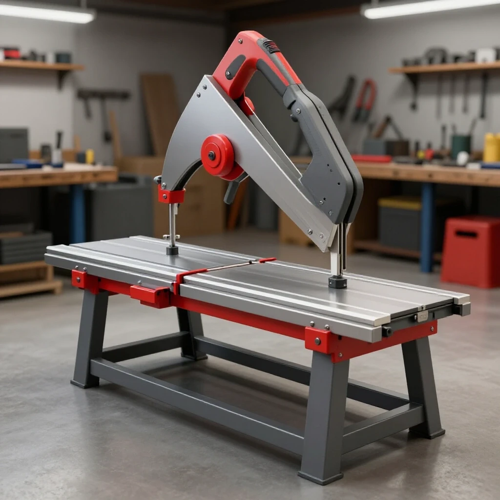
- Portaband: 1/16″ kerf. Great for cleaner cuts with less heat.
- Cold Saw: 3/32″ kerf. The gold standard for precision and minimal burrs.
| Cutting Tool | Kerf Width | Accuracy Level | Heat Input |
|---|---|---|---|
| Abrasive Chop Saw | 1/8″ | Moderate | High |
| Band Saw | 1/16″ | High | Low |
| Plasma Cutter | 3/16″ | Low | Very High |
| Oxy-Acetylene | 1/4″ | Low | Extreme |
Building Workshop Jigs and Fixtures for Alignment
A jig is a temporary structure or tool used to hold your workpieces in a fixed position during assembly.
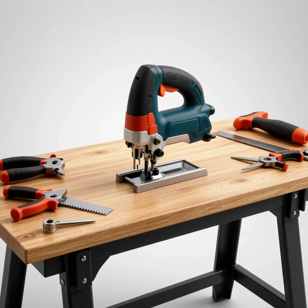
You cannot rely on your hands or a single magnet to keep a large frame square. As the metal heats up during welding, it will pull toward the heat source. To fight this, I use a flat layout surface—ideally a steel welding table, but a level concrete floor can work in a pinch. I create “stops” by clamping scrap blocks of angle iron to the table. These blocks act as a physical boundary that prevents the tubing from shifting as I work.
The 3-4-5 Rule for Square Layouts
Ensuring the outer tracks are perfectly parallel is the most critical part of this build. If the tracks taper inward by even 1/8th of an inch, the tray will lock up halfway out. I use the 3-4-5 triangle method to check for squareness on large frames. Measure 3 feet along one rail, 4 feet along the perpendicular rail, and the diagonal between those two points must be exactly 5 feet.
- Measure diagonals from corner to corner; they must be identical within 1/16″.
- Use heavy-duty C-clamps or F-clamps every 12 to 18 inches.
- Check for “twist” by sighting down the length of the rails to ensure they lie in the same plane.
Structural Tacking Strategies
A tack weld is a small, temporary weld used to hold components in place before the final beads are laid.
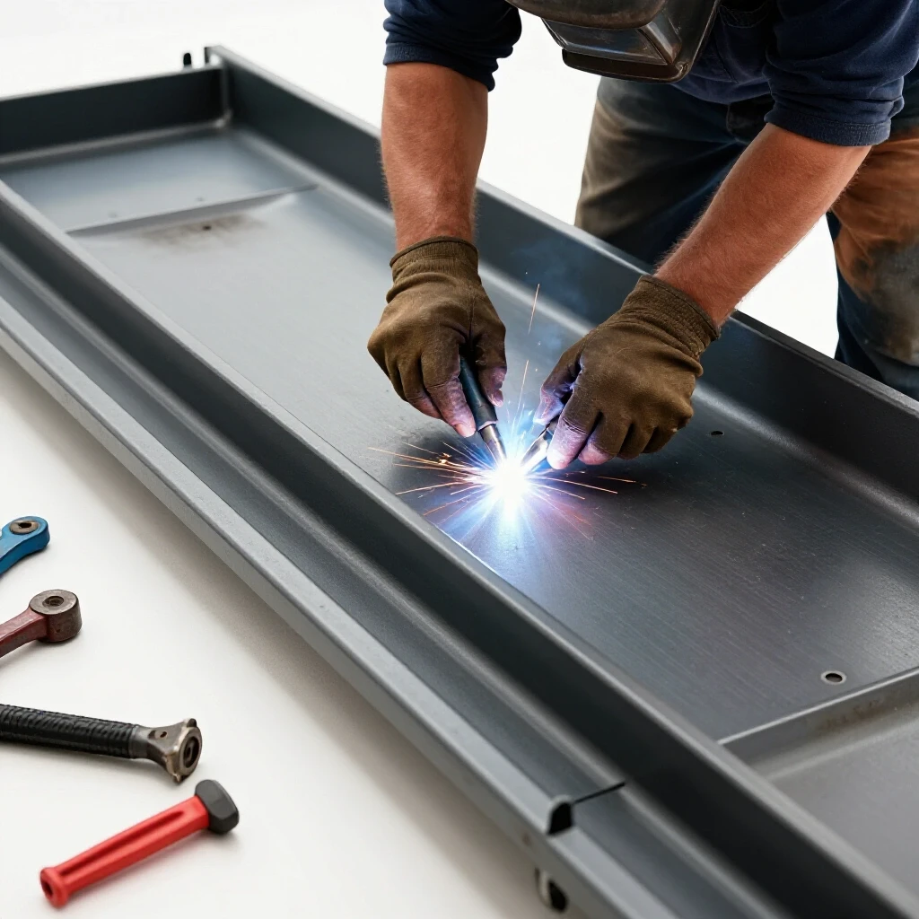
Many builders make the mistake of laying a full bead on one corner before move to the next. This is a recipe for a warped frame. Instead, you should place small, 1/4-inch tacks on the corners of every joint. For a sliding cargo tray, I recommend tacking the four corners of the main frame first, then re-measuring the diagonals. If the heat from the tacks pulled the frame out of square, you can easily break a small tack with a cold chisel and reset the joint.
Tack Spacing and Size Benchmarks
For 2″ square tubing, I place one tack on each of the four sides of the butt joint. I start with the “outside” corners because they are easier to adjust. Once the frame is tacked and verified square, I add “bridge tacks” across any gaps larger than 1/16″.
- Place a tack on the top-left corner.
- Place a tack on the bottom-right corner (diagonal opposite).
- Place a tack on the top-right.
- Place a tack on the bottom-left.
- Check for squareness again.
Managing Metal Warping Solutions through Weld Sequencing
Weld sequencing is the specific order in which you lay your final beads to balance the internal stresses caused by cooling metal.
When metal is liquid, it expands. As it cools and solidifies, it shrinks. This shrinkage exerts a massive mechanical pull on the surrounding steel. If you weld the entire top side of a frame first, the shrinkage will pull the ends of the rails upward, creating a “frown” shape. This is called angular distortion. To combat this, you must distribute the heat evenly across the entire structure.
The “Opposite Side” Technique
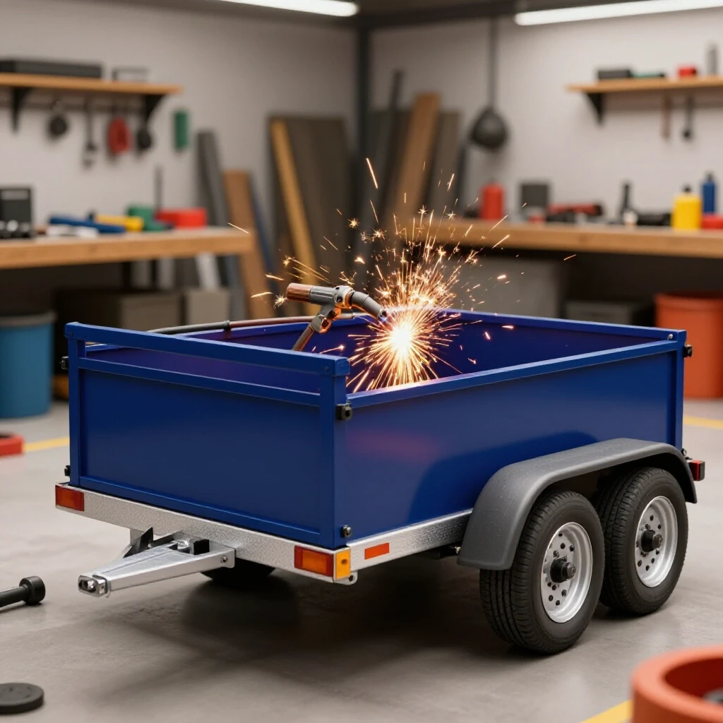
Building on the tacking strategy, the final welding should follow a balanced pattern. If I weld the outside vertical seam on the front-left corner, my next weld should be the outside vertical seam on the back-right corner. This “criss-cross” pattern helps cancel out the pulling forces.
- Step 1: Weld the short vertical seams on all four corners.
- Step 2: Flip the frame over and weld the corresponding seams on the bottom.
- Step 3: Weld the horizontal “top” seams in a staggered sequence.
- Step 4: Allow the metal to cool naturally. Never quench a structural weld with water, as this makes the steel brittle and increases warping.
| Weld Type | Shrinkage Force | Distortion Risk | Mitigation Strategy |
|---|---|---|---|
| Fillet Weld | High (pulls inward) | High | Use stiffeners or clamps |
| Butt Weld | Moderate (pulls together) | Medium | Maintain 1/16″ gap |
| Lap Weld | Low | Low | Use staggered tacks |
Bearing Integration and Track Alignment
The sliding mechanism relies on heavy-duty rollers, typically sealed ball bearings or cam followers, that ride inside a channel or along a rail.
For a heavy-duty tray, I prefer mounting the rollers to the stationary frame and having the tray slide over them. This keeps the moving part of the system simpler and lighter. When integrating these bearings, alignment is everything. If one bearing is 1/8″ higher than the others, it will carry the entire load, leading to premature failure or a “notchy” feel when sliding the tray.
Ensuring Smooth Travel
I use a long piece of cold-rolled flat bar as a straightedge to align the bearing mounting points. Cold-rolled steel is much straighter than hot-rolled steel because it is processed at room temperature, avoiding the scales and bows found in standard construction steel.
- Bearing Spacing: Place rollers every 18-24 inches along the stationary rails.
- Vertical Alignment: Use shims or adjustable mounting tabs to ensure all rollers sit at the same height within +/- 0.030 inches.
- Side Clearance: Leave a 1/8″ total gap between the tray sides and the outer tracks to account for minor debris or thermal expansion in the sun.
Reinforcing the Tray for Heavy Payloads
A flat tray made only of square tubing can flex in the middle when loaded with heavy tools or generators. To prevent this, you need to add structural webbing or a sheet metal skin that acts as a diaphragm.
I typically use 1/8″ tread plate (diamond plate) for the floor of the tray. Instead of welding a continuous bead around the perimeter—which would almost certainly warp the sheet—I use “stitch welding.” This involves laying a 1-inch bead every 6 inches. This provides plenty of strength while keeping the heat input low enough to prevent the sheet from “oil-canning” or buckling.
Structural Reinforcement Checklist
- Cross-members: Add 1.5″ x 1.5″ square tubing cross-members every 16 inches on center.
- Gussets: Weld triangular plates (gussets) into the corners of the main tray frame to prevent “racking” (parallelogram distortion).
- End Stops: Weld heavy-duty blocks at the end of the tracks to prevent the tray from sliding out of the truck entirely.
- Load Distribution: Ensure the weight of the tray is transferred to the truck bed floor through wide mounting feet rather than thin points of contact.
Correcting Heat Distortion After Welding
Even with the best fixtures and sequencing, some movement is inevitable. If you find your frame has a slight bow after it cools, there are ways to fix it without starting over.
The most common method is “flame straightening” or “mechanical cold-straightening.” If a rail is bowed upward, you can place the ends on blocks and apply pressure to the center using a heavy-duty hydraulic jack or a shop press. Alternatively, you can use a rosebud torch to heat a small “V” shape on the side opposite the bow. As that heated section cools, it will shrink and pull the rail back toward straight.
- Check with a String Line: Stretch a tight string from one end of the rail to the other to identify exactly where the bow begins.
- Incremental Pressure: When using a jack, apply pressure in small increments. Steel has an “elastic limit”; you have to push it slightly past its straight point so it “springs back” to the desired position.
- Heat Control: Never heat the steel to a bright white color; a dull cherry red (around 1,200°F) is sufficient for most straightening tasks.
Final Assembly and Testing Benchmarks
Before you consider the project finished, you must perform a dry fit. Slide the tray into the tracks without any grease or lubrication first. This allows you to hear and feel any spots where the metal might be rubbing.
If the tray slides smoothly with one hand, you have succeeded in maintaining your tolerances. If it requires a shove, look for shiny spots on the paint or metal; these indicate high points where the frame has warped or the alignment is off.
- Tolerance Check: Measure the width at the front, middle, and back of the tracks. They should be identical within 1/16″.
- Level Check: Ensure the tray sits level when fully extended. A drop of more than 1/2 inch at full extension may indicate a need for stiffer rails or closer bearing spacing.
- Stop Strength: Test the end stops with a firm pull to ensure they can handle the momentum of a loaded tray.
Summary of Best Practices for Custom Fabrication Projects
Success in building a sliding cargo system comes down to controlling the variables. By using accurate square cuts, robust workshop jigs and fixtures, and a disciplined weld sequencing layout, you can overcome the natural tendency of steel to warp.
- Always account for 1/8″ kerf when using a chop saw.
- Use the 3-4-5 rule and diagonal measurements to ensure a square foundation.
- Tack all joints before performing any final welding.
- Sequence your welds to balance heat and minimize angular distortion.
- Use stitch welding for sheet metal to prevent buckling.
- Verify your track parallelism at three points along the length.
Building your own utility equipment is a rewarding challenge. It requires a mix of engineering theory and hands-on problem-solving. While the heat of the welder will always try to pull your project out of alignment, these strategies give you the tools to pull it back into line and create a professional-grade sliding tray that will last for years.
FAQ: Frequently Asked Questions
How do I prevent my square tubing from twisting when I weld the corners? Twisting usually happens because one side of the joint is getting much hotter than the other, or the tacks are too weak. Use heavy-duty clamps to secure both pieces of tubing to a flat table. Place tacks on opposite corners (top-left, then bottom-right) to balance the initial pull.
What is the best way to ensure the two outer rails stay parallel? Cut two “spacer bars” from scrap tubing to the exact inside width you need between the rails. Clamp these spacers at the front and back of your tracks while you weld. This physically prevents the rails from drawing together as the metal cools.
Can I use an angle grinder for all my cuts? You can, but it is difficult to maintain a perfect 90-degree angle. If you use an angle grinder, use a square to mark all four sides of the tube and cut slowly. Be prepared to spend more time with a flap disc cleaning up the edges for a tight fit-up.
What size gap should I leave between the tray and the tracks? I recommend a total side-to-side clearance of 1/8″ to 1/4″. This “slop” is necessary because truck beds flex as you drive, and a tiny bit of debris in the track shouldn’t be enough to jam the entire system.
Why did my tray floor buckle after I welded it to the frame? This is caused by excessive heat. If you run a long, continuous bead, the sheet metal expands more than the thicker frame tubing. When it cools, it has nowhere to go but up or down. Use 1-inch stitch welds spaced 6 inches apart to keep the sheet flat.
How many bearings do I actually need for a 500-lb load? For a standard 5-foot to 6-foot bed, I recommend at least four heavy-duty bearings per side. This distributes the load so that no single bearing is stressed beyond its limit, especially when the tray is fully extended and leverage is at its peak.
Should I weld the bearings directly to the frame? No. It is better to weld a mounting stud or a bracket and then bolt the bearings on. This allows you to replace a bearing if it wears out or gets damaged, and it prevents the heat of welding from melting the internal seals or grease of the bearing.
How do I check for square if my tape measure is slightly off? The absolute measurement doesn’t matter as much as the comparison. Use the same tape measure for the entire project. If the diagonal from A to B is exactly the same as the diagonal from C to D, the frame is square, even if the tape measure itself is slightly inaccurate.
What wall thickness is best for the main tracks? For most DIY builds, 3/16″ is the “sweet spot.” It is thick enough to handle the point-load of the bearings without deforming, but not so heavy that it makes the tray impossible to install by yourself.
How do I fix a rail that has bowed outward? Place the rail on a sturdy surface with the “hump” facing up. Use a large C-clamp or a hydraulic press to push the center down while the ends are supported. You have to push it slightly past the straight point to account for the metal’s natural spring-back.
(This article was written by one of our staff writers, Robert Kline. Visit our Meet the Team page to learn more about the author and their expertise.)