Benchtop vs Floor Drill Press Accuracy Compared (Comparison)
I have spent fifteen years chasing thousandths of an inch across shop floors. There is a specific kind of frustration that sets in when you are halfway through a precision fabrication job and realize your holes are drifting. You might be using a high-end cobalt bit and a perfectly centered punch mark, but the exit hole on a two-inch block of 4140 steel is off by 0.015 inches. This is not a failure of the operator; it is a failure of the machine’s mechanical integrity. In my career as a millwright and diagnostic specialist, I have learned that the difference between a hole and a precision bore often comes down to the structural rigidity of the machine itself.
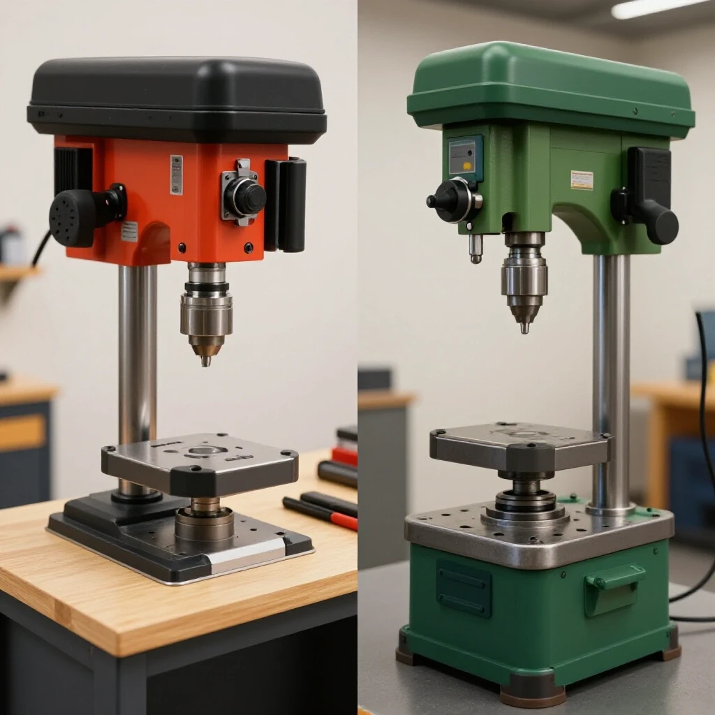
Whether you are working with a compact machine bolted to a wooden bench or a heavy-cast floor unit, the physics of drilling remain the same. The struggle usually begins when we assume the machine is a fixed, immovable object. In reality, every drill press is a series of joints and levers that can flex under pressure. I have seen fabricators lose days of productivity trying to troubleshoot weld porosity or tool chatter, only to realize the root cause was a spindle that tilted just enough under load to create an ovalized hole. By understanding how different machine frames handle stress, we can move away from guesswork and toward a systematic diagnostic approach.
The Foundation of Mechanical Precision and Rigidity
Mechanical precision in a drilling operation is the machine’s ability to maintain a perfectly perpendicular path while resisting the forces of the cutting bit. This involves the relationship between the spindle, the column, and the worktable. If any of these components flex, the accuracy of the cut is compromised immediately.
When I evaluate the precision of a compact drilling unit against a full-sized floor model, I start with the column. A shorter column on a bench-mounted unit is inherently stiffer because it has less distance to flex. However, floor models often compensate for their height with much larger column diameters and thicker wall sections. In my experience, a 2.5-inch diameter column on a bench model might seem sturdy, but it cannot match the vibration-damping mass of a 4-inch solid-wall floor column. This mass is critical because it absorbs the harmonic frequencies that lead to tool chatter.
If you are experiencing tool chatter solutions, the first thing to check is the machine’s resonant frequency. A lighter machine will often vibrate in sympathy with the drill bit’s flutes. This creates a “scalloped” pattern inside the hole. To diagnose this, I use a simple vibration logging template. I record the RPM where the chatter is most violent. If the chatter persists regardless of the RPM, the issue is likely a lack of rigidity in the machine frame rather than a simple tooling problem.
Isolating Spindle Runout and Quill Play
Spindle runout is the measurement of how much the center of the drill chuck deviates from the true axis of rotation. This is usually measured in thousandths of an inch using a dial indicator. Even a tiny amount of runout can cause a drill bit to “walk” or create holes that are significantly larger than the bit diameter.
In my diagnostic logs, I categorize runout into two types: static and dynamic. Static runout is what you measure when you turn the spindle by hand. Dynamic runout occurs when the machine is under load. I once worked on a case where a fabricator was struggling with a floor-standing unit that produced inconsistent hole sizes. We measured the static runout at 0.001 inches, which is excellent. However, when we applied 50 pounds of downward pressure—simulating a drilling load—the runout jumped to 0.008 inches.
The culprit was the quill fit. The quill is the sleeve that moves up and down within the headstock. If the tolerances between the quill and the headstock casting are too loose, the entire spindle assembly can tilt. This is a common mechanical troubleshooting step: extend the quill halfway, grab the chuck, and try to wiggle it. If you can feel movement, your accuracy is already gone. Benchtop units often have shorter quill travels, which can sometimes mean less leverage and less play, but they lack the heavy-duty bearings found in larger floor models.
Table Deflection and Support Geometry
The worktable is often the weakest link in the entire drilling system. It must support the weight of the workpiece and the downward force of the spindle without tilting. This is where the geometric differences between machine sizes become most apparent during a metalworking diagnostic guide.
Most benchtop machines use a simple rack-and-pinion system to move a cantilevered table. Because the table is only supported at the column, the front edge of the table can “nod” downward when you apply feed pressure. I have measured table deflection as high as 0.012 inches on light-duty machines during a standard drilling operation in 1/2-inch plate. This “nodding” causes the drill bit to enter the material at an angle, leading to a curved hole path.
Floor models typically feature larger tables with more robust support brackets. Some even include a secondary support jack or a “knee” similar to a milling machine. To test your table’s integrity, follow these steps:
- Mount a dial indicator to the spindle.
- Place the indicator tip on the outer edge of the table.
- Apply 40 to 60 pounds of pressure to the table by hand.
- Note the deviation on the dial.
If the table moves more than 0.003 inches under moderate pressure, you will never achieve high-precision results without reinforcing the setup. This lack of rigidity is a frequent cause of poor fitment in structural alignment faults, as the holes on mating parts won’t line up once the clamping pressure is released.
Comparing Vibrational Damping and Harmonic Stability
Vibration is the enemy of precision. In metal fabrication, vibration doesn’t just ruin the surface finish; it can also lead to premature tool failure and even contribute to issues like welding porosity if the base metal is improperly prepped with a vibrating tool.
The mass of a floor-standing drill press acts as a natural dampener. Think of it like a heavy anvil versus a light piece of sheet metal. When the drill bit hits a hard spot in the material, a heavy machine absorbs that shock. A lighter benchtop machine reflects that energy back into the spindle and the bit. This reflection is what causes tool chatter.
I often use a smartphone vibration spectrum analyzer to identify these resonant frequencies. By placing the phone on the headstock while the machine is running, I can see the peaks in the frequency graph. If I see a spike at a specific frequency, I know that is where the machine is most vulnerable. On floor models, these spikes are usually lower in frequency and lower in amplitude. On benchtop models, the spikes are often higher and sharper, which is much more damaging to carbide tooling.
Diagnostic Benchmarks for Drill Press Accuracy
To effectively compare the performance of these machines, we need hard data. In my workshop, I use a set of standardized benchmarks to determine if a machine is fit for high-tolerance work. These metrics help isolate whether a problem is caused by the machine’s design or a specific component failure.
| Measurement Category | Benchtop Tolerance (Target) | Floor Model Tolerance (Target) | Diagnostic Tool Used |
|---|---|---|---|
| Spindle Runout (Static) | < 0.003″ | < 0.0015″ | Dial Indicator |
| Quill Lateral Play | < 0.005″ | < 0.002″ | Dial Indicator / Manual Force |
| Table Deflection (50lb load) | < 0.010″ | < 0.004″ | Force Gauge + Indicator |
| Column Perpendicularity | 0.001″ per 6″ | 0.0005″ per 6″ | Precision Square / Tramming Tool |
| Spindle Backlash | < 0.005″ | < 0.002″ | Depth Micrometer |
If your machine falls outside these ranges, it is time for a mechanical alignment checklist. Start by checking the mounting bolts. A floor model that isn’t bolted to the concrete will vibrate more than a benchtop model that is properly secured. I have seen 800-pound machines behave like toys because they were sitting on uneven shop floors without shims.
Systematic Troubleshooting for Hole Deviation
When a hole goes crooked, most people blame the bit. While a dull bit can certainly cause issues, the machine’s alignment is more often the culprit. I follow a three-step isolation process: Observation, Isolation, and Variable Control.
First, observe the entry and exit points. If the entry is clean but the exit is offset, the spindle is likely not square to the table. This is known as being “out of tram.” To fix this, you must adjust the table until it is perfectly perpendicular to the spindle axis. This is similar to a lathe alignment checklist where you ensure the headstock and tailstock are on the same plane.
Second, isolate the movement. Use a dial indicator to check if the column itself is flexing. I once worked on a large floor press where the column was actually loose in the base casting. Every time the operator pulled the lever, the entire 4-inch steel pipe tilted back by half a degree. We had to clean the mating surfaces and re-torque the heavy-duty bolts to 120 ft-lbs to resolve the issue.
Third, control the variables. Use a consistent feed rate. If you are hand-feeding, you might be applying uneven pressure, which exacerbates any existing machine flex. For high-precision work, I always recommend using a mechanical feed if available, or at least a consistent “peck drilling” cycle to clear chips and reduce heat buildup. Excessive heat can cause material warping, which further complicates your accuracy measurements.
Addressing Tool Chatter and Surface Finish Issues
Tool chatter is more than an annoying sound; it is the physical manifestation of a machine reaching its limit. In my 18 years of troubleshooting, I’ve found that chatter on a benchtop machine is often due to a lack of “loop stiffness.” This is the stiffness of the entire path from the bit, through the spindle, up the column, and back through the table to the workpiece.
If you are facing tool chatter solutions, try these mechanical fabrication fixes:
- Reduce the overhang: Keep the quill retracted as much as possible. The further the quill extends, the more leverage the bit has to flex the spindle.
- Increase the mass: For benchtop units, I sometimes suggest clamping a heavy steel plate to the table. This adds temporary mass and helps dampen vibrations.
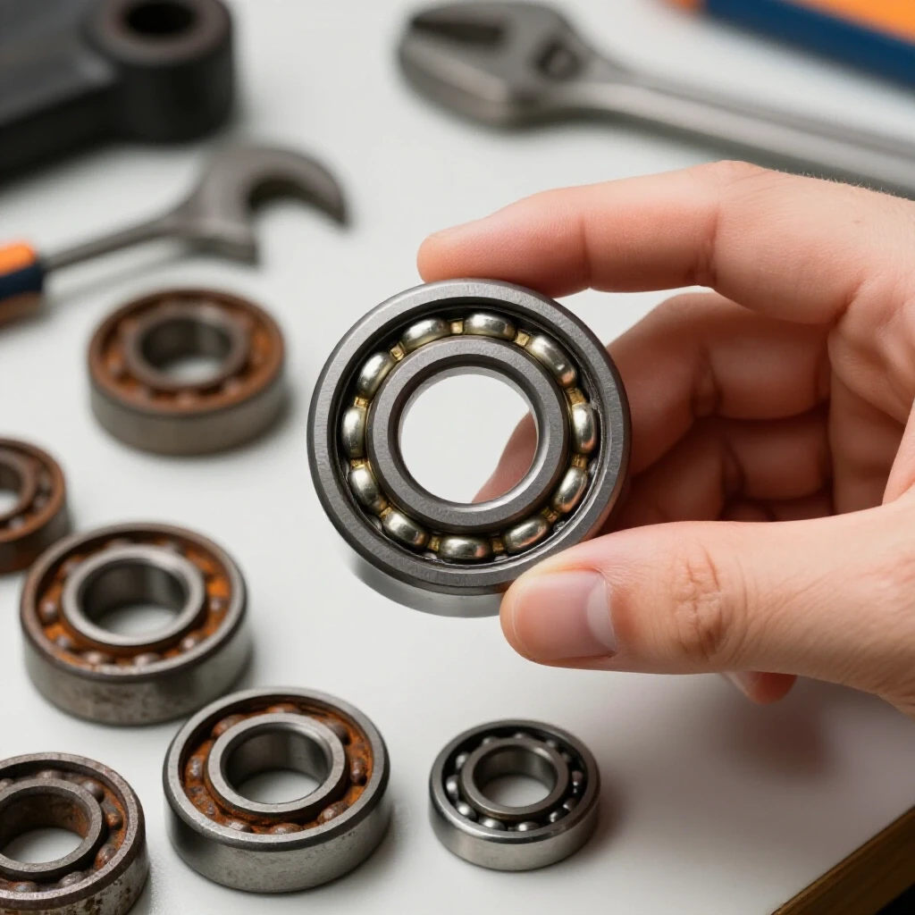
- Check the bearings: Worn spindle bearings are a primary source of high-frequency vibration. If the spindle feels “gritty” when you turn it by hand, the bearings are shot and no amount of alignment will save your accuracy.
In floor models, chatter is often caused by a loose table lock. Because the tables are heavier, operators sometimes forget to fully tighten the clamping handle. The weight of the table holds it in place for a moment, but as soon as the bit bites into the metal, the table begins to oscillate. Always ensure the table is locked tight to the column before starting a cut.
Case Study: The Mystery of the Ovalized Bores
I was once called into a shop that was producing custom hydraulic manifolds. They were using a heavy-duty floor drill press, but the bores were coming out slightly oval. The shop manager was convinced it was a metallurgical issue or a problem with the coolant. They had already spent thousands of dollars on different drill bits and shielding gas for their welding prep, thinking the material was hardening inconsistently.
I started by checking the spindle runout—it was perfect. I checked the table—it was rock solid. Then, I watched the operator work. He was drilling 1-inch holes in thick plate and was leaning into the handle with significant force. I set up a dial indicator on the headstock itself.
As it turned out, the headstock was sliding slightly on the column under heavy load. The locking bolts were tight, but the casting had a small amount of oil on the inside, allowing it to pivot a fraction of a millimeter when the torque peaked. We degreased the column, slightly roughened the clamping surface with 400-grit paper, and the ovality disappeared. This is why systematic troubleshooting is so vital; the problem wasn’t the tool or the metal, but a simple friction failure in the machine’s assembly.
Electrical and Motor Diagnostics
While we often focus on the mechanical aspects, the motor and drive system play a role in accuracy too. Inconsistent motor speed can lead to “surging” during a cut. This change in RPM affects the chip load on each tooth of the drill bit. If the RPM drops suddenly, the bit can grab the material, causing a massive spike in torque that flexes the entire machine.
On modern machines with variable frequency drives (VFDs), I check for back-EMF faults or current phase unbalance. If the motor isn’t receiving steady power, it won’t provide steady torque. For older machines, check the drive belts. A slipping belt is a common cause of tool chatter. When the belt slips and then grabs, it creates a vibration that travels straight down the spindle.
- Check belt tension: There should be about 1/2 inch of deflection under thumb pressure.
- Inspect pulleys: Look for “glazing” or shiny spots that indicate slipping.
- Monitor motor heat: An overheating motor will lose torque and cause speed fluctuations.
Finalizing Your Diagnostic Path
Mastering the accuracy of your drilling equipment requires a shift in mindset. You must stop seeing the machine as a static tool and start seeing it as a dynamic system of tolerances. Whether you are using a compact bench unit or a massive floor model, the goal is to eliminate variables.
Start by securing your base. A machine that moves is a machine that lies to you. Then, work your way up: the table, the column, the headstock, and finally the spindle. By using dial indicators and systematic testing, you can identify exactly where the flex is occurring. This data-driven approach is the only way to resolve hard-to-find issues like mechanical misalignments or persistent tool chatter.
Frequently Asked Questions
How much spindle runout is considered acceptable for general fabrication? For most metalworking tasks, a runout of 0.003 inches or less at the spindle is acceptable. If you are doing precision tool and die work, you should aim for less than 0.001 inches. Anything over 0.005 inches will cause noticeable issues with hole size and tool wear.
Can I make a benchtop drill press as accurate as a floor model? You can improve a benchtop model’s accuracy by reinforcing the bench it sits on and minimizing quill extension. However, you cannot easily replicate the vibration-damping mass of a floor model’s heavy castings. For light-duty, high-precision work, a benchtop model can be very accurate, but it will struggle with larger diameters where rigidity is paramount.
Why does my drill bit always wander even after I use a center punch? Wandering is usually caused by either a dull bit or spindle runout. If the spindle is not centered, the bit will rotate in a small circle rather than a single point. This makes it “jump” out of your center punch mark. Check your runout with a dial indicator.
What is the best way to check if my table is square to the spindle? This process is called tramming. Mount a dial indicator on an arm attached to the spindle. Rotate the spindle by hand so the indicator sweeps a wide circle on the table. If the reading changes as you move the indicator from the left side to the right side, your table is tilted.
Does column height really affect drilling precision? Yes, but perhaps not how you think. A taller column has more potential to flex like a long lever. However, floor models use much thicker columns to counteract this. A cheap floor model with a thin-walled column can actually be less rigid than a high-quality benchtop model with a short, thick column.
How do I fix a quill that has too much “slop” or lateral play? Some headstocks have a pinch-bolt or an adjustment screw that can tighten the fit of the quill. If your machine doesn’t have this, you may need to use a heavy-duty lubricant to take up some of the space, or in extreme cases, have the headstock bored and sleeved.
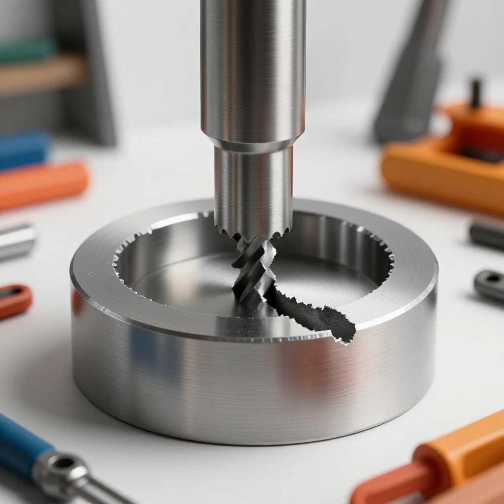
What causes the “scalloped” finish inside a drilled hole? This is almost always a result of resonant vibration or tool chatter. It happens when the machine’s rigidity isn’t high enough to resist the cutting forces. Try changing your RPM or increasing your feed pressure to “load” the machine and stop the vibration.
How often should I calibrate my drill press alignment? If you are doing precision work, I recommend a quick check every time you start a new project. For general shop use, a deep-dive alignment check every six months is usually sufficient, or whenever the machine has been moved or subjected to a heavy “crash.”
Can a loose drive belt affect the accuracy of my holes? Indirectly, yes. A loose belt causes inconsistent torque and RPM. This can lead to the bit grabbing and releasing the material, which creates vibrations that can flex the machine and ruin the hole’s internal finish.
Does the weight of the workpiece affect machine accuracy? On benchtop models, a very heavy workpiece can actually cause the table to sag before you even start drilling. Always ensure your table is properly supported. On floor models, the table is usually robust enough to handle significant weight without measurably tilting.
(This article was written by one of our staff writers, Paul Whitaker. Visit our Meet the Team page to learn more about the author and their expertise.)