Manual Metal Prep vs CNC Plasma Cutting Compared (DIY Guide)
I have spent more than two decades in the shop, moving from a small corner of a garage to a fully integrated manufacturing space. In the early days, my process was defined by the grit of a 4.5-inch angle grinder and the steady rhythm of a horizontal bandsaw. This manual approach is the foundation of our craft, but as my production needs grew, the physical toll and the time spent on repetitive tasks became a significant bottleneck. Scaling a fabrication business requires a shift in mindset from being a craftsman to acting as a process engineer. The move from hand-guided tools to a computer-controlled gantry is not just about speed; it is about reclaiming your time and improving the predictability of your output.
When I first integrated a CNC plasma system, I realized that my shop layout, which worked fine for manual work, was completely inadequate for automated workflows. I was moving heavy sheets of steel across the floor too many times, and my electrical system was straining under the new load. This guide reflects the lessons I learned while refining these systems. We will look at how to balance the traditional methods of shaping metal with the precision of automation, focusing on the infrastructure needed to make that transition successful.
Analyzing the Transition from Hand Tools to Automated Cutting
Moving from manual layout and cutting to an automated system involves shifting your primary labor from the shop floor to the computer desk. While manual methods rely on physical skill and hand-eye coordination, automated systems require digital precision and a focus on machine maintenance. This change affects your daily schedule and your physical fatigue levels.
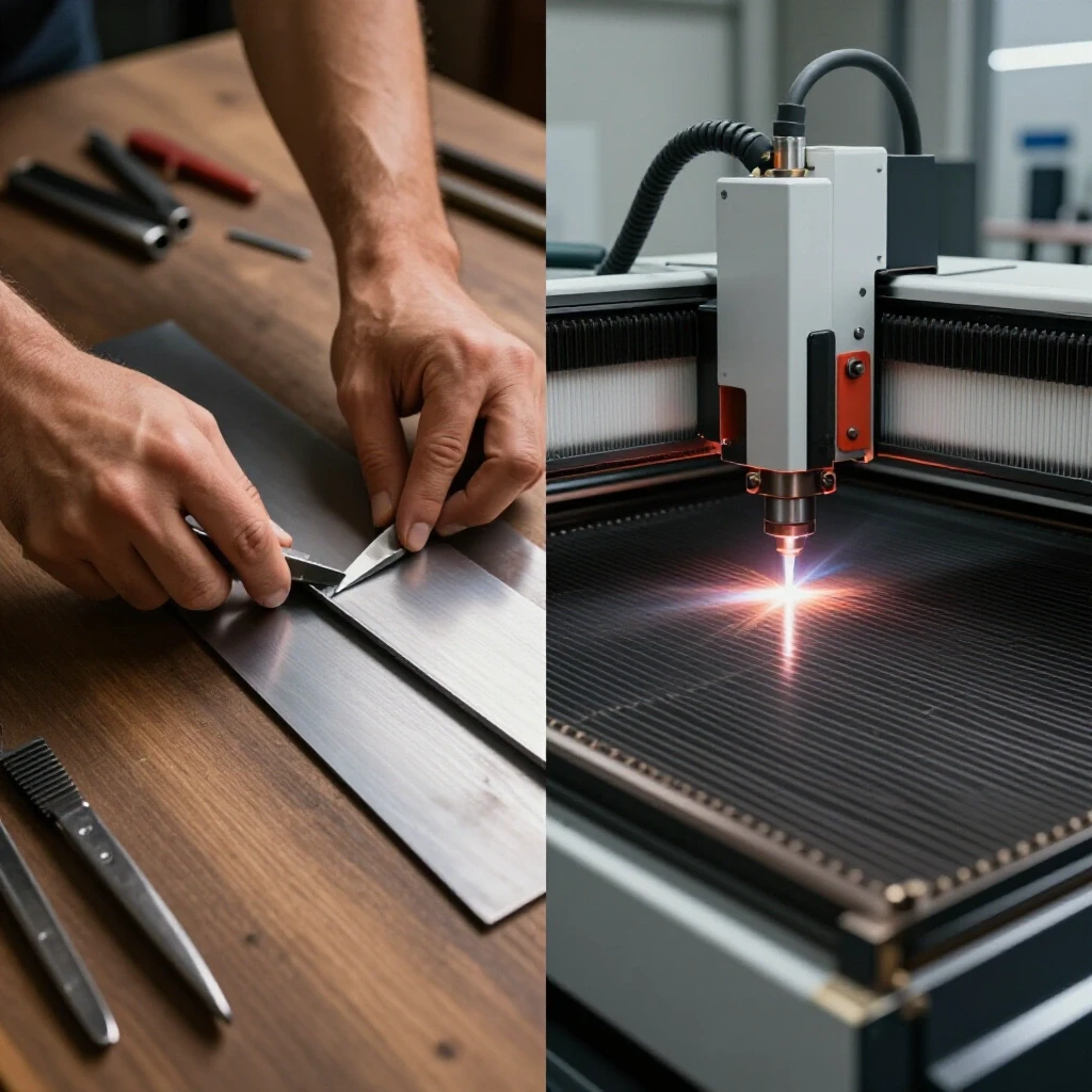
Manual metal preparation is a tactile process. You mark your lines with a scribe or soapstone, secure the material, and use a saw or torch to follow the path. It is flexible and requires little setup time for a single part. However, if you need to make ten identical brackets, the manual process becomes a liability. Automated cutting allows you to nest those ten parts on a single sheet, press a button, and walk away to handle other tasks. The trade-off is the time spent in the digital environment, where you must ensure your drawings are accurate before the torch ever touches the metal.
Comparing Physical Labor and Digital Planning
Digital planning replaces the physical strain of guiding a tool with the mental task of creating a cut path. In a manual setup, you are constantly adjusting for tool wear and heat distortion in real-time. With automation, these factors must be accounted for in your software settings before the operation begins.
In my experience, the learning curve is often the biggest hurdle. You are moving from a world of “feel” to a world of “coordinates.” If your digital file has a small gap in a line, the machine will stop or behave unexpectedly. This requires a level of attention to detail that is different from manual work. However, once a file is perfected, the machine will repeat that task with a consistency that a human hand simply cannot match over an eight-hour shift.
Accuracy Standards in Manual vs. Automated Workflows
Accuracy in manual cutting is limited by the thickness of your marking line and the steadiness of your hand. In contrast, automated systems move with a resolution measured in thousandths of an inch, though the actual cut quality is still influenced by the plasma arc physics.
While a CNC gantry can move very precisely, the plasma arc itself has a “kerf,” or width of the cut, that changes as the nozzle wears. To maintain high accuracy, you must monitor your consumables and adjust your software offsets. In manual work, you might aim for a tolerance of 1/16th of an inch. With a well-tuned automated system, you can consistently hit 1/32nd of an inch or better on mild steel up to 1/2 inch thick, which significantly reduces the time spent on secondary grinding and fit-up.
Optimizing Workshop Layout for Material Flow Efficiency
A successful shop layout minimizes the distance a piece of material travels from the rack to the finished pile. In a manual shop, tools are often grouped by type, but an automated workflow benefits from a linear path that prevents “back-tracking” across the floor.
When I redesigned my shop, I used a string-map technique. I traced the path a 4×8 sheet of steel took through my space. In the old manual setup, the sheet moved in a zig-zag pattern that wasted time and energy. By placing my material rack near the entry, followed by the cutting station, and then the welding area, I reduced my material handling time by nearly 30 percent. This is especially important as you scale, because moving heavy plate is one of the most dangerous and time-consuming parts of the job.
Mapping Material Travel Paths to Reduce Bottlenecks
A material travel path is the specific route a workpiece takes through your shop from raw stock to finished product. Identifying and shortening these paths reduces physical fatigue and speeds up production by eliminating unnecessary movement of heavy materials.
I recommend keeping a 3-foot minimum access zone around all sides of a CNC table. This allows you to load material from the side or the end and provides enough room for maintenance. In a manual setup, you might tuck a bandsaw against a wall, but an automated table needs space for the gantry to move and for you to clear out the dross and scrap that accumulates underneath.
| Layout Factor | Manual Setup | Automated Setup |
|---|---|---|
| Primary Work Zone | 4′ x 4′ per station | 10′ x 12′ (for 4×8 table) |
| Material Handling | Manual lifting/carts | Jib crane or forklift access |
| Tool Storage | Near workbench | Integrated with CNC station |
| Scrap Management | Small bins | Large under-table cleanout |
Machine Zoning and Floor Load Ratings
Machine zoning involves grouping equipment based on the type of debris they produce and their utility requirements. Floor load ratings refer to the weight a concrete slab can support, which is critical when adding heavy water tables and gantry systems.
A 4×8 plasma table with a water bed can weigh several thousand pounds when full. I had to verify that my shop floor was at least 4 inches of reinforced concrete to prevent cracking. Additionally, I zoned my “hot” and “dirty” processes—like plasma cutting and grinding—away from my “clean” areas where I do assembly or electronics work. This prevents metallic dust from settling into sensitive components or ruining a fresh paint job.
Managing Electrical Loads and 3-Phase Power Integration
Most residential or small commercial shops have single-phase power, but high-output fabrication equipment often performs better or requires 3-phase power. Managing these electrical loads is essential to avoid tripping breakers or damaging sensitive CNC electronics.
When I added my first heavy-duty plasma power source, I realized my single-phase panel was at its limit. 3-phase power provides a more consistent delivery of energy, which is vital for the high-amperage draw of a plasma arc. If you don’t have utility 3-phase, you have to look at conversion options. Balancing the voltage between phases is the key to keeping your motors running cool and your electronics stable.
Understanding Rotary and Digital Phase Converters
A phase converter takes single-phase input and creates a third leg of power to mimic 3-phase utility service. Rotary converters use a physical motor to generate the third leg, while digital converters use solid-state electronics for a cleaner power signal.
- Rotary Phase Converters (RPC): These are robust and can handle the high inrush current of large motors. However, they can be noisy and the voltage balance can shift depending on the load.
- Digital Phase Converters: These offer the most stable voltage and are ideal for CNC equipment. They are more expensive but protect the sensitive drives and controllers on your gantry.
- Static Converters: I generally advise against these for CNC work, as they only provide 3-phase power during startup and lead to a significant loss of motor torque.
Calculating Electrical Phase Balances for Stability
Phase balancing is the process of ensuring that the voltage across all three legs of a 3-phase system is as equal as possible. Unbalanced phases can cause heat buildup in motors and inconsistent arc quality in plasma cutting.
I use a multimeter to check my voltages under load. According to the National Electrical Code (NEC), you want your phases to be within 2 to 5 percent of each other. If one leg is significantly lower, your CNC motors might vibrate or lose steps, which ruins your parts. I keep a log of these readings every six months to ensure my converter is still performing correctly as I add more tools to the circuit.
Designing High-Volume Air Filtration and Fume Management
Metalworking produces two types of airborne hazards: heavy dust from grinding and fine particulate smoke from plasma cutting. A professional shop must have a ventilation strategy that handles both to protect the operator and the equipment.
In my early years, I just opened the garage door. That doesn’t work when you are cutting for four hours straight. Plasma smoke is composed of microscopic metal particles that linger in the air and settle on everything. I had to design a system that moved at least 1,000 to 2,000 Cubic Feet per Minute (CFM) to keep the air clear. This involves a combination of source collection at the table and general air scrubbing for the rest of the shop.
CFM Requirements and Duct Static Pressure
CFM measures the volume of air moved, while static pressure is the resistance that air meets as it travels through ducts. High static pressure, caused by long runs or too many bends in the pipe, can significantly reduce the effectiveness of your fan.
For a standard plasma table, I recommend a “downdraft” or “water table” approach. A downdraft table requires a high-pressure blower to pull smoke through the slats and out of the building. To calculate your needs, you look at the surface area of the table. A 4×8 table usually needs about 3,000 CFM if it isn’t partitioned into smaller zones. By using smooth-walled metal ducting instead of flexible ribbed hose, I was able to maintain higher air velocity and keep the dust from settling in the pipes.
Implementing Multi-Stage Cyclone Dust Collection
A cyclone separator uses centrifugal force to drop heavy particles into a bin before the air reaches the fine filters. This multi-stage approach prevents your expensive HEPA filters from clogging every few days.
- Stage 1: The cyclone removes 95 percent of the heavy grinding dust and large sparks.
- Stage 2: A pleated filter captures the fine plasma smoke particles down to 0.5 microns.
- Stage 3: An optional carbon filter can help reduce the smell of burnt metal and coatings.
I found that adding a silencer to my collection system was a game-changer. It allowed me to keep the ventilation running without the constant roar that leads to operator fatigue.
Evaluating the Capital and Operational Costs of Automation
The decision to move toward automated cutting is a financial one. You must weigh the initial purchase price against the long-term savings in labor and the increase in your shop’s total capacity.
When I analyzed my own shop’s data, I looked at “machine uptime.” In a manual setup, the tools only work when I am holding them. With the CNC gantry, the machine can be cutting while I am prepping the next sheet or answering emails. However, you must also account for “consumables”—the electrodes and nozzles that the plasma torch eats through. These are a recurring cost that doesn’t exist with a simple bandsaw blade.
Capital Amortization and Tooling ROI
Amortization is the process of spreading the cost of an expensive machine over its useful life. Return on Investment (ROI) is the point at which the machine has paid for itself through increased profits or saved labor hours.
- Calculate the total cost: Include the machine, shipping, electrical upgrades, and software.
- Estimate time savings: If the machine saves you 10 hours a week at a shop rate of $75/hour, that is $750 a week in value.
- Determine the break-even point: Divide the total cost by the weekly savings to see how many months it will take to pay off the investment.
In my case, the transition to automation paid for itself in less than 18 months. The ability to take on more complex projects that I previously turned down was a major factor in that success.
Maintenance Intervals for CNC Systems
Regular maintenance prevents the “hidden costs” of downtime. An automated system has more moving parts than a manual saw, including lead screws, linear rails, and electronic sensors that require attention.
- Daily: Wipe down linear rails and check air compressor filters for moisture.
- Weekly: Check the squareness of the gantry and tighten any loose belts or couplers.
- Monthly: Inspect the electrical cabinet for dust buildup and test the emergency stop systems.
- Quarterly: Grease all bearings and check the water table for pH balance to prevent corrosion.
I keep a clipboard next to the controller to track these intervals. Skipping a simple rail cleaning can lead to a “stutter” in the machine’s movement, which results in a jagged cut and a wasted piece of expensive plate.
Software Integration and the Digital Workflow
The bridge between your idea and a finished metal part is the software. This involves three steps: CAD (Computer-Aided Design), CAM (Computer-Aided Manufacturing), and the machine controller.
For many years, I struggled with the “digital wall.” I was used to drawing on the steel itself. Learning to think in terms of layers and vectors was a challenge. However, modern cloud-based CAD systems have made this much easier. You can design a part on your tablet in the house and have it ready to cut by the time you walk out to the shop. This integration is what truly turns a hobby shop into a professional-grade operation.
Transitioning from Hand Sketches to CAD/CAM
CAD is where you draw the part, and CAM is where you tell the machine how to cut it (setting lead-ins, speeds, and torch height). Moving from a hand sketch to a digital file requires a shift in how you handle measurements and tolerances.
I recommend starting with simple shapes to understand how the “offset” works. The software needs to know that the torch has a width, so it moves the center of the torch slightly outside your line to ensure the part comes out the right size. If you ignore this, every part you cut will be slightly too small. Once you master this, you can begin “nesting” parts, which means arranging them on the sheet to minimize waste. This is where the real efficiency gains are found.
Conclusion and Next Steps for Shop Evolution
Transitioning from manual metal preparation to an automated CNC workflow is a significant milestone for any fabricator. It requires a strategic look at your shop’s layout, power, and air quality systems. While the technical learning curve can be steep, the reward is a shop that operates with higher precision and less physical strain.
My advice is to take it one step at a time. Start by optimizing your material flow and upgrading your electrical service before the machine arrives. This ensures that when you finally fire up the gantry, the rest of your shop is ready to support the increased output. Focus on the data—track your time, your costs, and your accuracy. This systematic approach is what separates a crowded hobby space from a highly efficient, professional workshop.
FAQ
What is the biggest difference in floor space needs between manual and CNC setups? Manual tools like grinders and saws are compact but require a large “swing area” for long pieces of metal. A CNC plasma table has a fixed footprint but requires clear access on at least three sides for loading full sheets and performing gantry maintenance. You generally need about 150 to 200 square feet dedicated solely to a 4×8 table setup.
How do I know if I need a 3-phase converter for my shop? Check the data plate on your plasma power supply. If it requires 3-phase power, or if your single-phase service is less than 200 amps, you will likely need a converter. 3-phase is more efficient for high-amperage cutting and provides a smoother arc, which improves cut quality.
Can I use a standard shop vac for plasma smoke? No. Plasma smoke particles are too fine for a standard shop vac and will quickly clog the filter or pass right through it. You need a dedicated high-volume blower (1,000+ CFM) and a multi-stage filtration system or a water table to effectively manage the fumes.
What is “kerf” and why does it matter for accuracy? Kerf is the width of the material removed by the plasma arc. It is usually between 0.040 and 0.060 inches. In manual cutting, you compensate for this by “leaving the line.” In CNC cutting, the CAM software automatically adjusts the torch path based on the kerf width you input.
How much maintenance does a CNC plasma table really need? Unlike a manual bandsaw that might only need a new blade occasionally, a CNC table requires daily cleaning of the rails and moisture checks in the air lines. Weekly checks of the gantry squareness and monthly lubrication of the drive system are essential for consistent accuracy.
Is the software hard to learn for someone used to manual work? The logic is different, but the concepts of measurement are the same. Most fabricators find that the “CAM” portion—setting up the cut—is the steepest part of the curve. Many modern programs offer “auto-nesting” and “toolpath optimization” that handle much of the heavy lifting.
What is a water table, and do I need one? A water table is a tray under the cutting slats filled with water and a rust inhibitor. It captures about 90 percent of the dust and sparks, and it helps cool the metal to prevent warping. It is a simpler, quieter alternative to a high-volume downdraft exhaust system.
How does automated cutting affect my material costs? Initially, you might waste more material as you learn the software. However, once you understand nesting, you will significantly reduce waste by fitting more parts onto a single sheet than you ever could by hand-marking.
What is the most common mistake when setting up a CNC gantry? Neglecting the air quality. If your compressed air has moisture or oil in it, your plasma consumables will fail prematurely, and your cut quality will be poor. A high-quality air dryer is just as important as the plasma cutter itself.
Can I cut 1/2 inch steel with a home-based CNC setup? Yes, provided your plasma power source has the amperage (usually 65-85 amps) and your table is rigid enough to handle the weight. You must also ensure your floor can support the weight of the plate and the water table.
(This article was written by one of our staff writers, Edward Sinclair. Visit our Meet the Team page to learn more about the author and their expertise.)