How to Analyze and Prevent Welded Joint Failure Points (Fix)
I remember the first time a project of mine failed. It was a heavy-duty engine stand I had built during my second year in the shop. On paper, the steel was thick enough, and the beads looked decent. But as soon as we bolted a big-block V8 onto it, I heard a sharp, metallic “crack.” One of the vertical supports had snapped right at the toe of the weld. It didn’t fail because the steel was weak; it failed because I hadn’t respected the way force moves through a joint.
Fourteen years later, I treat every weld as a data point. In my time inspecting industrial frames and building custom shop equipment, I have learned that most failures happen long before you pull the trigger on the torch. They happen during the design and preparation phases. If you are working in a home shop, the stakes are high because you are often the designer, the fabricator, and the safety inspector all at once.
Mastering Stress Distribution in Metal Assemblies
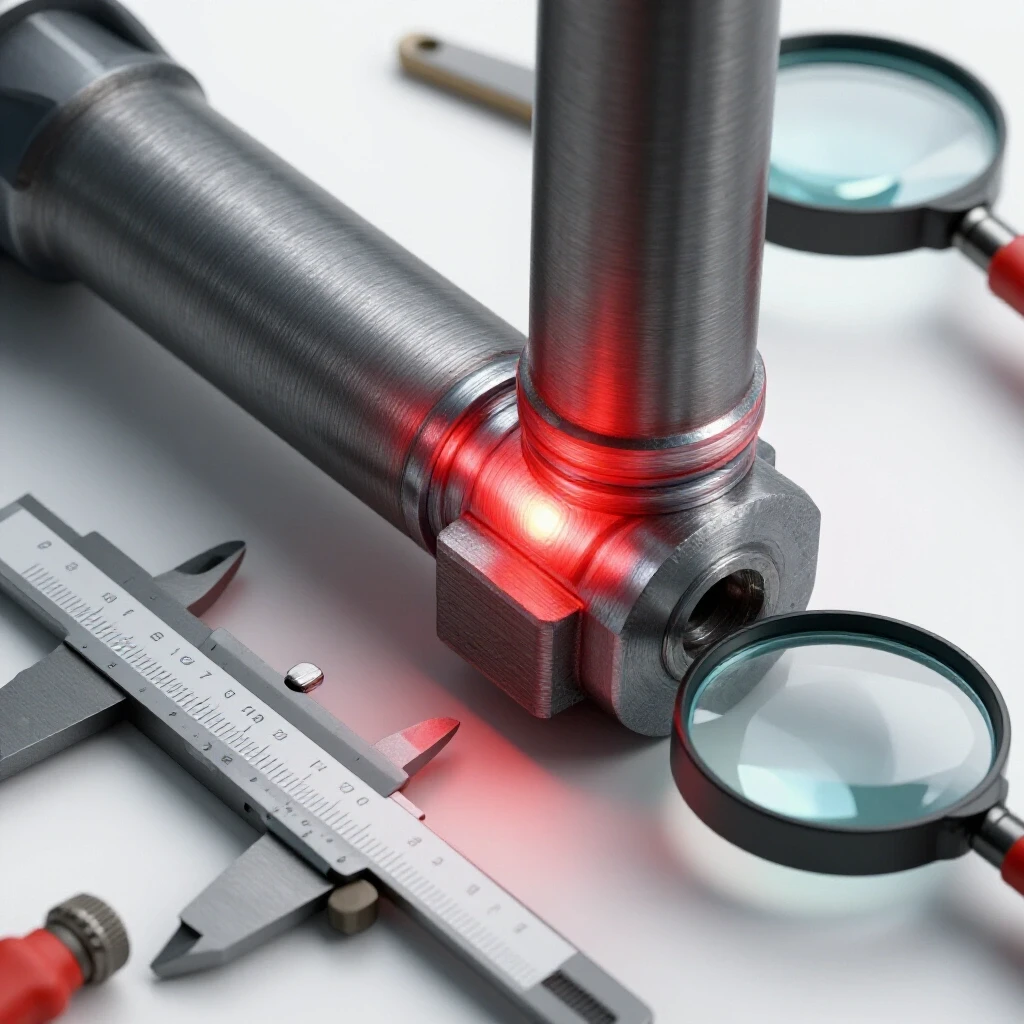
Stress distribution refers to how physical loads move through a metal part and its connections. In a well-designed joint, the force flows smoothly across the assembly without bunching up in one spot. When stress concentrates in a single corner or a poor weld, it exceeds the metal’s limit and causes a break.
Understanding structural metal load capacity starts with visualizing how weight travels. Think of force like water flowing through a pipe. If the pipe has a sharp 90-degree turn with a rough interior, the water creates turbulence and pressure at that corner. Metal acts the same way. If you have a sharp corner with a heavy weld bead that hasn’t been tapered, the stress “piles up” at the edge of the weld.
In my workshop, I use a simple 2:1 or 4:1 safety factor. This means if I expect a shelf to hold 500 pounds, I design it to handle 1,000 or even 2,000 pounds. This margin accounts for the reality that my manual welds might not be as perfect as a robotic factory arm.
- Tension: Pulling force that tries to stretch the joint.
- Compression: Pushing force that tries to crush the joint.
- Shear: Sliding force that tries to “scissor” the weld apart.
| Load Type | Risk Level in Small Shops | Prevention Strategy |
|---|---|---|
| Tension | High | Use full-penetration welds and avoid “butt” joints for heavy loads. |
| Compression | Low | Ensure square cuts so the metal faces touch and transfer weight directly. |
| Shear | Medium | Use gussets or “fish plates” to spread the sliding force over more area. |
Optimizing Joint Preparation for Deep Fusion
Joint preparation is the process of cleaning, beveling, and fitting metal pieces together before you start welding. Proper “prep” ensures that the filler metal actually mixes with the base metal throughout the entire thickness of the piece. Without this, you end up with a “cold” weld that is essentially just hot glue sitting on top.
If you are working with material thicker than 1/8 inch, you cannot just butt two flat edges together and expect a strong bond. I always grind a “V” or a “U” shape into the edges. This creates a valley for the molten metal to fill. For a standard 1/4-inch plate, a 30-degree bevel on each side is a good baseline.
Cleaning is the other half of the battle. Rust, mill scale, and oil are the primary enemies of garage fabrication safety. They introduce impurities into the weld pool that cause tiny bubbles. I use a dedicated flap disc or a wire wheel to get the metal to a “bright white” finish at least one inch back from the weld zone.
- Beveling: Grind the edges to a 30-60 degree total included angle.
- Root Gap: Leave a small space (about the width of your welding wire) between the pieces.
- Cleaning: Remove all gray mill scale until the steel is shiny.
- Tacking: Use small, strong “tack welds” every few inches to prevent the metal from pulling out of alignment as it heats up.
Managing the Heat Affected Zone Weakness
The heat affected zone, or HAZ, is the area of the base metal that was not melted but was heated enough to change its internal structure. This heat often makes the metal around the weld softer or more brittle than the rest of the piece. Most structural cracks start in the HAZ rather than the weld itself.
When I inspect a failed part, the break is almost always right next to the weld bead. This is because the high heat from the torch acted like a localized heat treatment. To minimize heat affected zone weakness, you need to control how much energy you put into the metal. This is known as “heat input.”
If you stay in one spot too long or run your welder at a higher amperage than necessary, the HAZ grows larger. For risk-averse fabricators, the goal is to weld fast enough to get fusion but slow enough to maintain a consistent bead. I often use “stitch welding”—welding a few inches in one spot, then moving to a different part of the project—to let the first area cool down.
- Color Check: If the metal turns a deep blue or purple far away from the weld, you are using too much heat.
- Cooling: Never quench a structural weld in water to cool it down. This “shocks” the metal and makes the HAZ extremely brittle. Let it air cool.
- Backing Bars: On thin material, use a copper or thick steel block behind the joint to soak up excess heat.
Identifying and Fixing Internal Weld Defects
Welding defect troubleshooting involves looking for physical flaws like porosity, undercut, and lack of fusion. Porosity looks like tiny holes or “Swiss cheese” in the weld, while undercut is a groove melted into the base metal right at the edge of the bead. Both of these are major failure points.
Porosity is usually caused by poor welding gas flow rate or wind blowing your shielding gas away. In a home shop, I recommend a flow rate of 15–20 CFH (cubic feet per hour). If you go too high, you create turbulence that sucks in air; too low, and you don’t have enough protection.
Undercut is a “mechanical notch.” It acts like a perforated line on a piece of paper, telling the metal exactly where to tear. It happens when your travel speed is too fast or your voltage is too high for the thickness of the metal.
| Defect | Visual Sign | Root Cause | Fix |
|---|---|---|---|
| Porosity | Tiny surface holes | Dirty metal or low gas flow | Clean metal; check for drafts; set gas to 18 CFH. |
| Undercut | Groove at the weld edge | Too much heat or wrong torch angle | Lower voltage; pause slightly at the edges of the bead. |
| Lack of Fusion | Weld looks “rolled over” | Too little heat or wrong angle | Increase amperage; ensure the arc hits the joint root. |
| Cracking | Thin line down the center | High internal stress or rapid cooling | Pre-heat thick metal; allow slow air cooling. |
Implementing Workshop Safety and PPE Standards
Garage fabrication safety requires a disciplined approach to personal protective equipment (PPE) and shop layout. Because welding produces intense ultraviolet light and toxic fumes, your gear must be rated for the specific task at hand. A “near-miss” in the shop is usually a sign that a safety protocol was skipped.
I always use a smart welding helmet with a variable shade. For most MIG or Stick welding on steel, a Shade 10 to 13 filter is the standard. If you find yourself with “sand in the eyes” feeling at night, your shade is either too light or your helmet isn’t reacting fast enough.
Ventilation is another critical factor. I never weld in a completely closed garage. Even a small fan positioned to pull smoke away from your face (not blow it across the weld) makes a massive difference. According to OSHA-style guidelines for small spaces, you want to ensure a constant exchange of fresh air to prevent the buildup of argon or CO2.
- Eye Protection: Auto-darkening helmet (Shade 10-13) plus safety glasses underneath for grinding.
- Skin Protection: Flame-resistant (FR) jacket and leather gloves. Never leave skin exposed to UV rays.
- Respiratory: Use a P100 rated respirator if welding on galvanized steel or in poorly ventilated areas.
- Fire Safety: Keep a fire extinguisher within arm’s reach and clear all sawdust or flammable liquids from the “spark zone” (about 20 feet around the welder).
Practical Methods for Testing Weld Integrity
You don’t need a million-dollar lab to verify that your joints are safe. Simple, non-destructive testing (NDT) kits and manual “destructive” tests can provide the confidence you need. These methods help you see what is happening inside or on the surface of the metal that the naked eye might miss.
One of my favorite tools is a dye penetrant kit. You spray a red dye on the weld, wipe it off, and then apply a white developer. If there is a microscopic crack, the red dye will “bleed” through the white powder. It is an affordable way to check critical structural points on things like trailers or lifting jigs.
For practice pieces, I highly recommend the “bend test.” Take two pieces of scrap, weld them together using your chosen settings, and then put them in a large vise. Use a heavy hammer or a press to bend the joint 90 degrees. If the weld snaps or peels off like a scab, you have a fusion problem. If the metal bends but the weld stays intact, you have a solid process.
- Visual Inspection: Use a flashlight and a magnifying glass to look for cracks or pinholes.
- Dye Penetrant: Use a three-part kit (cleaner, dye, developer) for surface cracks.
- Magnetic Particle: For steel, use a strong magnet and fine iron filings to find hidden surface breaks.
- The “Ring” Test: Tap a large steel assembly with a hammer. A solid weld produces a clear “ring,” while a cracked or hollow weld often produces a dull “thud.”
A Framework for Shop Success
To ensure my projects stay together, I follow a strict verification checklist. This takes the guesswork out of the process and reduces the anxiety of “is it strong enough?”
- Step 1: Material Verification. Is the steel grade appropriate? (ASTM A36 is the standard for most shop projects).
- Step 2: Machine Calibration. Is the wire speed and voltage set according to the chart inside the welder door?
- Step 3: Gas Check. Is the tank open and the flow rate set to 15-20 CFH?
- Step 4: Fit-up Inspection. Is the gap consistent? Are the bevels clean?
- Step 5: Post-Weld Audit. After the metal cools, I check for undercut and use a weld gauge to measure the “throat” or thickness of the bead.
By treating the fabrication process as a series of controlled steps, you move away from “hoping it holds” and toward “knowing it will.” In my 14 years on the floor, I’ve found that the most talented fabricators aren’t the ones with the flashiest tools; they are the ones who are the most disciplined about the basics.
Frequently Asked Questions
Why does my weld have tiny holes in it after I finish a bead? This is called porosity. It happens when the molten metal is exposed to air. The most common causes are a low welding gas flow rate, a draft in your shop blowing the gas away, or failing to clean the mill scale and oil off the steel before you started.
Is it safe to weld on a painted or rusty surface? No. Welding over paint, rust, or zinc (galvanized) coating creates toxic fumes and leads to brittle welds with poor fusion. Always grind the metal down to a shiny, bare surface at least one inch away from where you plan to weld.
How do I know if I am using too much heat? Watch for “undercut,” which is a visible groove or “shelf” eaten into the base metal at the edge of your weld. Also, look at the heat-tint (the rainbow colors). If the blue and purple colors extend several inches away from a small weld, your heat input is likely too high, which can weaken the metal.
What is the “Heat Affected Zone” and why should I care? The HAZ is the area right next to your weld that got hot but didn’t melt. This heat changes the metal’s molecular structure. If you get it too hot or cool it too fast, this area becomes the weakest point of your project and is where most cracks will start.
What shade should my welding helmet be set to? For most DIY and intermediate projects (MIG or Stick welding between 100-200 amps), a Shade 10 or 11 is standard. If you are welding at higher amperages, move up to a Shade 12 or 13 to protect your eyes from “arc flash” and long-term damage.
Can I use a fan to stay cool while welding? You can, but do not point it directly at your work area. A fan blowing across your weld will strip away the shielding gas, leading to porosity and a weak joint. Point the fan so it pulls smoke away from you from behind or from the side, away from the arc.
How do I prevent my project from warping or twisting? Metal expands when hot and shrinks as it cools. To prevent warping, use plenty of strong tack welds before doing the final pass. You can also use “back-stepping” (welding in short sections in the opposite direction of the overall travel) to balance the heat.
What is the best way to test my welds at home? The most effective home test is a “bend test” on scrap pieces. Weld two pieces together and try to break them in a vise. If the metal bends without the weld cracking, your settings are good. For finished projects, a dye penetrant kit is a great way to check for surface cracks.
Why did my weld crack right down the middle as it cooled? This is often a “centerline crack.” It usually happens because the weld bead was too thin and narrow for the thickness of the metal, or the joint was under too much tension. Increasing your bead size or pre-heating the metal can help prevent this.
Is a 110v welder strong enough for structural projects? A 110v (household plug) welder is generally limited to 1/8-inch or 3/16-inch steel. If you are building something structural like a car trailer or a heavy hoist, you should use a 220v welder to ensure you get deep enough penetration into the thicker steel.
(This article was written by one of our staff writers, James Harlan. Visit our Meet the Team page to learn more about the author and their expertise.)