How to Build a Heavy Duty Slatted Plasma Cutting Table (Fix)
I have spent over a decade in prototype shops and backyard garages, and I have learned one thing the hard way: metal has a memory, and it is usually a stubborn one. There is nothing more frustrating than spending hours meticulously measuring and cutting stock for a new workshop fixture, only to watch the frame twist into a trapezoid as soon as the last weld cools. I remember building my first utility trailer; I was so focused on the strength of the beads that I ignored the sequence. By the time I was done, the rear gate didn’t even line up with the latch.
That experience taught me that successful custom fabrication projects are not just about the quality of the weld, but about managing the physics of heat. When you are constructing a heavy-duty station to support thermal cutting operations, you are dealing with a structure that will face constant heat cycles. If the frame is not built with rigid geometry and a smart assembly plan, it will warp, and your work surface will never be flat. This guide focuses on the technical steps to build a durable, slatted support system that remains square and functional under heavy use.
Planning the Framework for a Rigid Cutting Support
Planning is the stage where you decide how your project will handle the stresses of both weight and heat. A well-designed cutting station needs to be more than just a table; it must be a stable platform that allows for debris clearance and provides a flat reference for your workpieces.
Designing a cutting list involves more than just listing lengths; it requires accounting for the thickness of your material and the gaps needed for weld penetration. I always start with a detailed blueprint that includes “cut-to-fit” markers. For a support frame, I prefer using 2×2 inch square tubing with a 3/16-inch wall thickness. This provides enough mass to act as a heat sink without making the table impossible to move.
Understanding Material Selection and Thermal Mass
Material selection involves choosing the right steel shapes and thicknesses to resist bending and heat-induced distortion. Heavier sections provide more thermal mass, which helps dissipate heat more slowly, reducing the risk of localized warping during the assembly of custom fabrication projects.
When I select materials, I look at the “Moment of Inertia” of the profiles. Square tubing is excellent for resisting twisting (torsion), while C-channel is great for the outer perimeter because it allows for easy clamping of workshop jigs and fixtures. For the internal slats, 1/8-inch or 3/16-inch flat bar is the standard. It is thick enough to support heavy plate but thin enough to be easily replaced when the arc eventually eats through it.
Calculating Kerf and Cutting Allowances
Kerf is the width of the material that is turned into dust or slag during the cutting process. In accurate metal layout tips, calculating kerf is essential to ensure that your finished components meet the required dimensional tolerances of +/- 1/16th inch.
If you are using a cold saw, your kerf might be 1/8 inch. If you are using an abrasive chop saw, it could be closer to 3/16 inch. I always mark my steel with a scribe or a fine-point silver pencil on the “waste” side of the line. If you cut down the middle of the line, your part will be short by half the width of the blade. Over a four-sided frame, those small errors add up to a structure that is out of square.
| Cutter Type | Typical Kerf Allowance | Precision Level |
|---|---|---|
| Cold Saw | 0.080″ – 0.120″ | High |
| Abrasive Chop Saw | 0.125″ – 0.187″ | Moderate |
| Band Saw | 0.035″ – 0.050″ | Very High |
| Handheld Torch | 0.150″ – 0.250″ | Low |
Establishing a Square Layout and Building Workshop Jigs
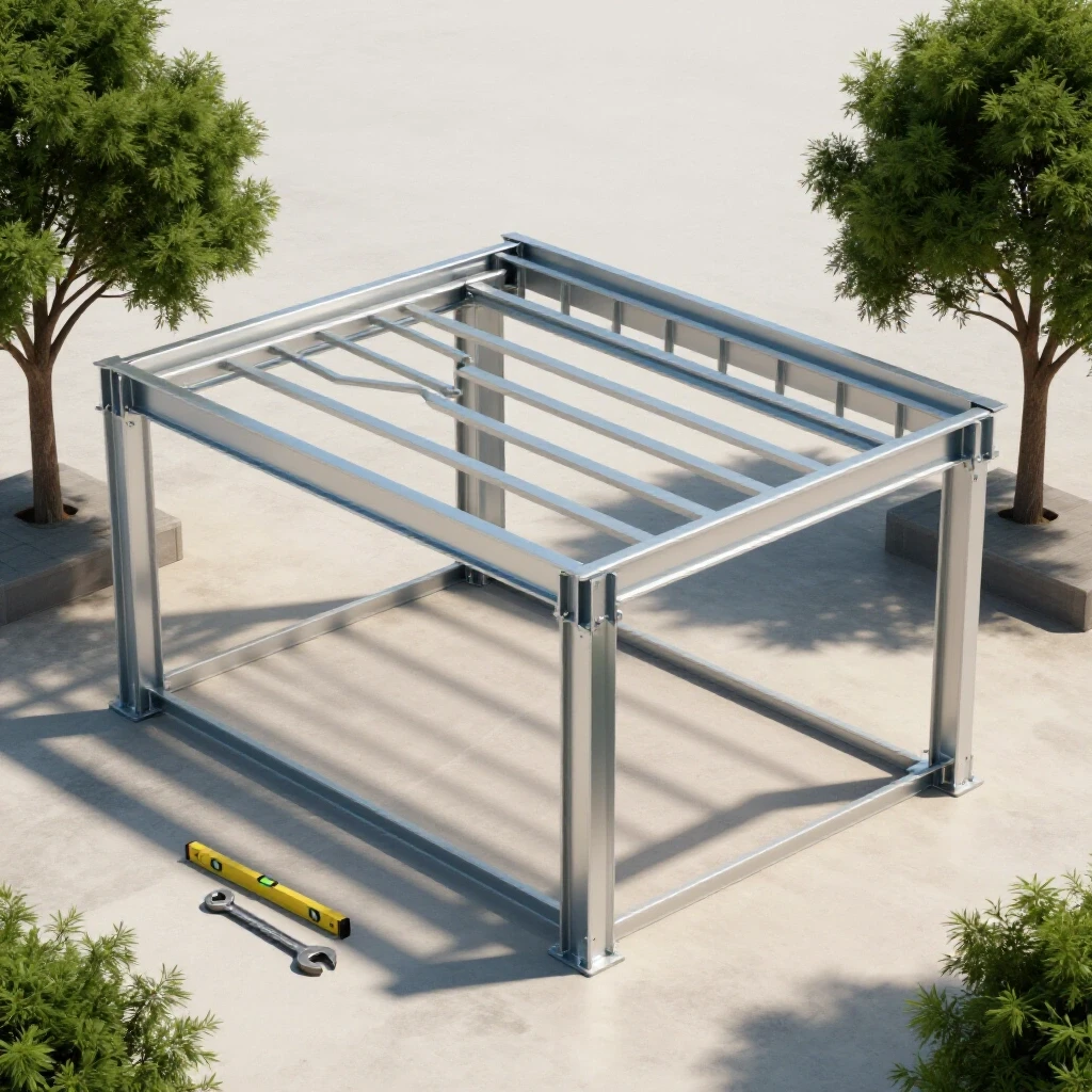
The secret to a straight build is a flat starting point. Most garage floors are sloped for drainage, which means you cannot rely on them for leveling a frame. I use a dedicated layout table or a set of leveled sawhorses to ensure the base is on a single plane.
Before I strike an arc, I build a simple corner jig. This is just two pieces of heavy angle iron welded at a 90-degree angle to a base plate. By clamping my frame members into this jig, I can ensure that the corners stay put while I apply my initial tacks. This is a foundational step in creating workshop jigs and fixtures that actually work.
The Importance of Squaring the Perimeter
Squaring the perimeter is the process of ensuring all four corners of a rectangular frame are exactly 90 degrees. This is verified by measuring the diagonals from corner to corner; if the measurements are identical, the frame is square.
I always aim for a diagonal tolerance of within 1/16 of an inch. If one diagonal is 60 inches and the other is 60-1/4 inches, the frame is “racked.” To fix this, I use a ratcheting cargo strap or a long bar clamp across the long diagonal to pull the frame into alignment before I commit to more than two tack welds per corner.
Clamping Strategies for Distortion Control
Clamping strategies involve using physical force to hold metal parts in a specific position to resist the pulling forces of a cooling weld. Effective clamping prevents “angular distortion,” where the heat causes the vertical members to pull toward the bead.
- Use F-style clamps every 12 to 18 inches along a joint.
- Place scrap blocks of wood or metal under the center of a long span to “pre-bend” it slightly against the direction of the expected warp.
- Always clamp to a rigid reference surface like a thick steel table or a heavy I-beam.
Managing Heat Warp with Strategic Weld Sequences
Weld sequencing layout is the most critical part of the build. When you weld, the metal expands as it heats and contracts as it cools. Because the cooling process happens more slowly than the heating, the weld “pulls” the surrounding metal. If you weld all the way around one corner before moving to the next, you will pull the frame out of alignment.
I use a “staggered” approach. I start with small, 1/4-inch tacks on all four corners. Then, I move in a cross-pattern, similar to how you tighten lug nuts on a car wheel. This distributes the heat evenly across the entire structure, allowing the stresses to cancel each other out.
The Role of Tack Welding in Structural Integrity
Tack welds are small, temporary welds used to hold components in place before the final beads are laid. They must be strong enough to resist the initial thermal expansion but small enough to be easily ground out if an error is discovered.
For a heavy-duty cutting support, I place tacks at each corner of the tubing. I prefer to put them on the “neutral axis” of the steel—the center of the side wall—where they have the least amount of leverage to pull the frame out of square. I usually make my tacks about 3/16 of an inch in diameter.
Executing the Back-Step Welding Technique
The back-step technique involves welding in the opposite direction of the overall progress of the bead. Instead of one long continuous pass, you lay short segments, starting each new segment where the previous one began, which helps minimize longitudinal shrinkage.
Building on this, I also alternate sides. If I weld the top of the left rail, my next weld is the bottom of the right rail. This “seesaw” method of heat application is one of the most effective metal warping solutions I have found in my 13 years of fabrication. It keeps the “pull” balanced.
| Weld Sequence Step | Action | Purpose |
|---|---|---|
| 1. Initial Tacking | 1/4″ tacks at all 4 corners | Hold geometry |
| 2. Diagonal Check | Measure corner-to-corner | Verify squareness |
| 3. Root Passes | Short beads on opposing sides | Balance initial stress |
| 4. Vertical Wraps | Weld the upright faces | Structural strength |
| 5. Final Caps | Finish the top surfaces | Aesthetics and seal |
Designing the Slat System for Debris and Slag Management
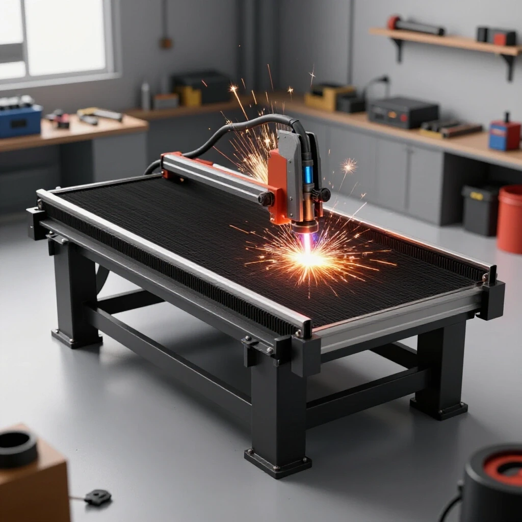
The slats are the heart of a thermal cutting table. They need to support the weight of your project while allowing the sparks and molten metal (slag) to fall through to a collection area. If the slats are too close together, slag will bridge the gap and weld your workpiece to the table. If they are too far apart, small parts will fall through or tilt.
I recommend a slat spacing of 2 to 3 inches. This provides a good balance for most custom fabrication projects. I also design the slats to be “floating” or held in notched channels. This makes them easy to flip over when the top edge gets notched by the torch, doubling their lifespan.
Creating Replaceable Slat Inserts
Replaceable slat inserts are individual bars of steel that sit in a notched frame, allowing for easy removal and replacement. This modular design ensures the main frame remains intact even as the support surface is gradually consumed by the cutting process.
I use a simple “comb” layout. I cut notches into the long sides of the inner frame using a 1/8-inch cutting disc. The slats simply slide into these notches. Interestingly, I don’t weld the slats in place. Leaving them loose allows them to expand and contract freely as they get hit by the cutting arc, which prevents the main frame from warping over time.
Slag Clearance and Downward Airflow
Downward debris clearance refers to the space beneath the slats that allows molten metal and sparks to dissipate without bouncing back up or accumulating against the frame. A minimum of 12 inches of open space below the slats is ideal for safety and cleanliness.
In my shop, I built a funnel-shaped tray (a “slag hopper”) that sits under the slats. This catches all the hot metal and directs it into a removable bucket. This not only keeps the floor clean but also reduces the fire hazard in a garage environment.
Final Alignment and Post-Weld Straightening
Even with the best sequencing, some movement is inevitable. Once the frame is fully welded and has cooled to room temperature (never check for square while it is still hot), it is time for the final alignment check.
If I find a slight bow in a rail, I use “flame straightening.” This involves heating a small spot on the convex (protruding) side of the bend with an oxy-acetylene torch. As that spot cools, it shrinks more than the surrounding metal, pulling the rail back into a straight line. It is a technique that requires patience, but it is a lifesaver for achieving accurate square cuts and straight frames.
Using Modern Tools for Verification
While a tape measure and a framing square are the old-school standards, modern laser alignment tools have become very affordable for the home builder. A simple cross-line laser can help you verify that your slats are on the same horizontal plane across the entire 4-foot or 5-foot span of the table.
I also use a digital protractor to check the verticality of the legs. If a leg is leaning by even half a degree, it can make the table feel unstable when you are loading a heavy sheet of 1/2-inch plate steel.
Maintenance and Longevity of the Cutting Surface
A heavy-duty support station is an investment in your shop’s capability. To keep it in good shape, I periodically run a heavy-duty wire brush over the slats to knock off the slag “grapes.” If a slat gets too badly damaged, I just pull it out and drop in a new piece of flat bar.
- Rotate slats every 3-4 months to even out the wear.
- Keep the slag hopper empty to prevent heat buildup under the table.
- Check the frame bolts (if using a modular design) for tightness after the first few heavy heat cycles.
Summary of Key Fabrication Benchmarks
To ensure your project is a success, keep these benchmarks in mind throughout the build process:
- Dimensional Tolerance: Aim for +/- 1/16 inch on all frame lengths.
- Squareness: Diagonals must match within 1/16 inch before final welding.
- Tack Spacing: Place tacks every 2-4 inches on long joints to prevent gapping.
- Cooling Time: Allow the frame to reach ambient temperature before removing clamps.
- Slat Leveling: Ensure all slats are within 1/32 inch of the same height to prevent workpiece “rocking.”
Building a high-quality support system for your metalwork is a rite of passage for many fabricators. It requires a shift in mindset from “just sticking metal together” to “managing thermal forces.” By following a strict weld sequence and using a modular slat design, you can create a tool that will serve your shop for decades.
FAQ
What is the best material for the replaceable slats? Mild steel flat bar (1/8″ or 3/16″ thick) is the most common choice. While stainless steel resists slag better, it is significantly more expensive and tends to warp more violently under heat. Mild steel is cost-effective and easy to source.
Should I weld the slats to the frame? No, I highly recommend against welding the slats. If you weld them, the heat from the cutting process will transfer directly into your main frame, causing it to warp over time. Using a notched “comb” system allows the slats to expand independently.
How do I prevent the table from wobbling on an uneven garage floor? The best solution is to weld heavy-duty threaded bungs into the bottom of the legs and use 1/2-inch or 5/8-inch leveling feet. This allows you to adjust each corner individually to compensate for the slope of your floor.
What height should a fabrication cutting table be? Most builders find that a height of 34 to 36 inches is comfortable. This is roughly the same height as a standard kitchen counter or workbench, which reduces back strain when leaning over to guide a torch.
How much gap should I leave between the slats? A 2-inch to 3-inch gap is the “sweet spot.” It provides enough support for smaller parts so they don’t tip over, but it is wide enough that you aren’t constantly hitting a slat with your cutting arc.
Why did my frame warp even though I clamped it down? Clamping only holds the metal in place while it is clamped. If the internal stresses from the weld are high enough, the metal will spring into a warped shape as soon as you release the clamps. This is why weld sequencing and back-stepping are more important than clamping force alone.
Can I use aluminum for the slats? Aluminum has a much lower melting point than steel. If you use a plasma torch or oxy-fuel over aluminum slats, you will melt them almost instantly. Stick to mild steel for the support surface.
How do I clean the slag off the slats? A heavy-duty chipping hammer or a pneumatic needle scaler is very effective. Some builders also use a dedicated “slag scraper”—a heavy piece of steel plate with a handle—to knock the dross off the top edges of the slats.
Is it necessary to paint the frame? I recommend painting the main frame with a high-heat primer and paint to prevent rust, but do not paint the slats themselves. The paint on the slats will burn off during the first use, creating toxic fumes and a mess.
How do I ensure the slats are all at the same height? When you cut the notches for the slats, use a jig or a template to ensure the depth of every notch is identical. If the notches are consistent, the slats will naturally sit at the same level.
(This article was written by one of our staff writers, Robert Kline. Visit our Meet the Team page to learn more about the author and their expertise.)