How to Build a Rigid Mount Table for Tool Sharpeners (Guide)
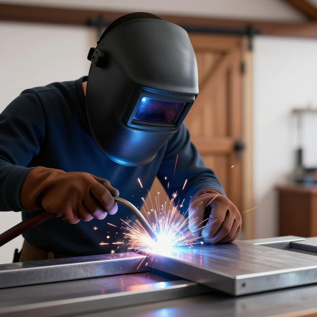
I have spent over a decade in prototype shops and home garages, and I have learned one thing the hard way: metal has a mind of its own. You can measure three times and cut once, but the moment you strike an arc, the laws of physics take over. I remember building a heavy-duty base for a precision grinder early in my career. I didn’t plan my weld sequence, and by the time I finished the last bead, the top plate had pulled nearly an eighth of an inch out of level. For a sharpening station, that kind of error makes the whole project useless.
Building a stable, vibration-resistant platform for your sharpening tools requires more than just sticking metal together. It requires a deep understanding of how heat moves through steel and how to use mechanical force to keep things square. In this guide, I will walk you through the process of fabricating a solid mounting station, focusing on layout accuracy, heat control, and structural integrity.
Designing the Foundation for a Vibration-Resistant Base
Designing a heavy-duty tool stand involves selecting materials that provide mass and rigidity to dampen vibrations during the sharpening process. Using heavy-walled square tubing or thick angle iron ensures the frame can support the weight of a steel top plate and the tool itself without flexing.
When I plan custom fabrication projects, I start with a detailed cut list that accounts for every fraction of an inch. For a sharpening table, mass is your friend. A heavier stand absorbs the micro-vibrations from the grinding wheel, which leads to a cleaner edge on your tools. I typically recommend 2-inch square tubing with a 3/16-inch wall thickness for the legs and 1/4-inch plate steel for the mounting surface.
Before you buy your steel, you must calculate your total dimensions based on the tool’s footprint. If your sharpening jig requires a 12-inch by 12-inch space, your top plate should be at least 14 inches square to allow for clamping and bolt holes. Always leave a small margin for error in your material estimates to account for the thickness of the metal itself.
Material Preparation and Calculating Kerf Allowances
Material preparation is the process of cleaning and cutting steel to exact specifications while accounting for the material lost during the cutting process. Accurate square cuts are the foundation of a successful build, as gaps in the fit-up lead to excessive weld shrinkage and structural weakness.
One of the biggest mistakes I see in garage shops is ignoring the kerf. The kerf is the width of the material that the saw blade turns into dust. If you use a standard abrasive chop saw, your kerf might be nearly 1/8 of an inch. If you have four cuts in a row and don’t account for that, your final piece will be half an inch too short.
| Cutting Tool Type | Typical Kerf Width | Dimensional Tolerance |
|---|---|---|
| Abrasive Chop Saw | 3/32″ to 1/8″ | +/- 1/16″ |
| Cold Saw | 1/16″ to 3/32″ | +/- 1/32″ |
| Horizontal Band Saw | 0.035″ to 0.050″ | +/- 1/64″ |
| Plasma Cutter (Manual) | 1/16″ to 1/8″ | +/- 1/8″ |
After cutting, you must prep the joints. I use a flap disc to remove mill scale—the dark grey coating on hot-rolled steel—at least one inch back from every weld zone. Welding over mill scale causes porosity and weak bonds. I also grind a 30-degree bevel on any material thicker than 1/8 inch to ensure the weld penetrates deep into the root of the joint.
Creating Accurate Layouts with Workshop Jigs and Fixtures
A workshop jig is a temporary structure or setup used to hold workpieces in the correct position during assembly and welding. Using a flat reference surface, such as a thick steel welding table or a heavy-duty workbench, allows you to clamp parts down and prevent them from moving as you work.
I never trust my eyes to determine if a corner is square. I use heavy steel squares and dedicated layout fixtures. For a tool stand, I often build a simple “L-jig” out of scrap angle iron. I clamp this jig to my table and then clamp my frame pieces into the jig. This forces the parts to stay at a 90-degree angle while I apply my first tacks.
If you don’t have a professional fixture table, you can use the floor of your shop if it is level, but a raised table is better for your back and your accuracy. I use “F-style” clamps every 6 to 8 inches along a joint to ensure there is no daylight between the mating surfaces. Even a tiny gap will cause the metal to pull more aggressively when the weld cools.
The Science of Weld Shrinkage and Metal Warping Solutions
Metal warping occurs because steel expands when it is heated and contracts as it cools. Since the weld bead is molten, it occupies more space than it will when it reaches room temperature; as it solidifies, it pulls the surrounding metal toward the center of the weld.
Understanding angular pull is vital. If you weld only one side of a T-joint, the upright piece will lean toward the weld. To combat this, I use a technique called “presetting.” I might lean the part a few degrees away from the weld so that as the bead cools, it pulls the part into a perfectly square position. However, this takes experience to master.
A more reliable method for most builders is to use mechanical restraint. I clamp the part to a massive heat sink—like a 1-inch thick steel plate—to soak up the heat and hold the geometry. The faster the heat leaves the weld zone, the less time the surrounding metal has to expand and distort.
Implementing a Strategic Weld Sequencing Layout
Weld sequencing is the specific order in which you apply beads to a structure to balance the internal stresses caused by heat. By jumping from one side of the frame to the other, you allow the shrinkage forces to cancel each other out rather than stacking up in one direction.
When I am fabricating a rectangular frame for a mounting station, I never finish one corner before moving to the next. I follow a “criss-cross” pattern, similar to how you tighten lug nuts on a car tire. This distributes the heat evenly across the entire structure.
| Sequence Step | Action Taken | Purpose |
|---|---|---|
| 1. Primary Tacks | Small tacks at the outside corners of all four joints. | Sets the basic footprint. |
| 2. Secondary Tacks | Tacks on the inside corners and midpoints. | Locks the squareness in place. |
| 3. Root Passes (Side A) | Short 1-inch beads on the top of corner 1 and corner 3. | Balances initial pull across the diagonal. |
| 4. Root Passes (Side B) | Short 1-inch beads on the top of corner 2 and corner 4. | Completes the diagonal balance. |
| 5. Vertical Wraps | Welding the vertical faces in a rotating order. | Prevents the legs from “toeing in.” |
I generally use tack welds that are about 1/4 inch to 3/8 inch long. If a tack is too small, the cooling force of the main weld will snap it. If it is too large, it becomes difficult to weld over smoothly. I space my tacks about 2 inches apart on critical joints.
Constructing the Frame: From Tacking to Final Beads
The assembly phase begins with a “tack-and-check” strategy where you secure the frame with minimal heat before verifying all dimensions. This allows you to break a tack with a hammer or grinder if you find the frame has pulled out of square before the permanent welds are laid.
I start by building the two side “ladders” of the stand. I lay the legs and cross-members on the table, clamp them flat, and tack the corners. I then measure the diagonals. If the distance from the top-left corner to the bottom-right corner is exactly the same as the top-right to the bottom-left, the frame is square. I aim for a tolerance of +/- 1/16th of an inch.
Once the side ladders are square, I stand them up and connect them with the front and back rails. This is where a second set of hands or a magnetic square is helpful. I tack the top rails first, check for square again, and then tack the bottom stretchers. Only after the entire 3D skeleton is tacked and measured do I begin the final welding sequence.
Integrating the Top Plate and Ensuring a Flat Surface
The top plate of a sharpening station must be as flat as possible to ensure the tool’s base doesn’t rock or vibrate. Attaching a large plate to a frame often causes the plate to “oil-can” or bow in the middle due to the heat of the perimeter welds.
To prevent this, I don’t weld a continuous bead around the entire plate. Instead, I use “stitch welding.” I lay a 2-inch bead, skip 4 inches, and lay another 2-inch bead. I move from the center of the rail outward to the corners. This allows the plate to expand and contract without warping the center of the mounting surface.
If the plate is very thick (1/2 inch or more), I may drill holes through the plate and “plug weld” it to the frame cross-members. This provides extra rigidity in the center of the table. After welding, I use a straight edge to check for high spots. If a small amount of warping occurs, I can usually shim the tool when I bolt it down to ensure it sits perfectly level.
Drilling and Mounting for Long-Term Stability
Once the fabrication is complete, the final step is to drill the mounting holes for the sharpening equipment. Precision drilling in thick steel requires high-quality cobalt bits and a slow drill speed with plenty of cutting fluid to prevent overheating the tool steel.
I prefer to bolt my tools down rather than welding them directly to the table. This allows me to swap out equipment or adjust the position if I upgrade my sharpening system later. I use Grade 5 or Grade 8 bolts with nylon-insert lock nuts to ensure that the vibrations of the tool don’t loosen the fasteners over time.
I also recommend adding adjustable leveling feet to the bottom of the legs. Very few garage floors are perfectly flat. By using threaded inserts and heavy-duty leveling pads, you can ensure the table doesn’t wobble, which is essential for precision sharpening. A wobbling table is not just annoying; it’s a safety hazard when you are working with high-speed grinding wheels.
Lessons from the Shop: A Case Study in Distortion
A few years ago, I built a similar stand for a heavy belt grinder. I was in a rush and decided to weld the entire top plate in one go, starting at one corner and circling the perimeter. By the time I was halfway done, I could see the plate lifting off the frame. The heat had nowhere to go, and the expansion forced the metal to bow upward.
I had to cut the welds, grind everything flat again, and restart. That mistake cost me four hours of labor and a wasted grinding disc. Now, I always use the “touch-and-go” method. I feel the metal near the weld; if it’s too hot to touch for more than a second, I stop and move to a different part of the project. Patience is the most important tool in custom fabrication projects.
Final Inspection and Maintenance
After the metal has cooled completely—and I mean completely, as metal continues to move until it reaches room temperature—I do a final sweep with a square and a level. I check every joint for cracks or undercut. Undercut is a groove melted into the base metal next to the weld, which can act as a stress riser and lead to failure under vibration.
I finish the project by wiping the steel down with a degreaser and applying a light coat of paste wax or a simple rust-preventative spray. Since this is a utility project, I’m more concerned with function than fashion, but preventing rust ensures the mounting surface stays smooth for years to come.
Actionable Framework for Your Build
- Draft Your Cut List: Include every piece of tubing and plate. Subtract your kerf (usually 1/8″) from your total material purchase.
- Prep the Joints: Grind off all mill scale. Bevel edges on 1/4″ plate.
- Square the Sub-Assemblies: Build the sides first. Measure diagonals to within 1/16″.
- Tack Heavily: Use 1/4″ long tacks. Space them every 2-3 inches on the top plate.
- Sequence the Heat: Jump across the frame. Never weld two adjacent corners in a row.
- Stitch Weld the Top: Use 2-inch beads with 4-inch gaps to prevent the plate from bowing.
- Level the Feet: Use adjustable pads to compensate for uneven shop floors.
Frequently Asked Questions
Why does my metal always pull out of square even when I clamp it?
Clamps can only do so much. When the weld cools, the microscopic grain structure of the steel literally shrinks. If you don’t have enough tacks or if your tacks are too small, the shrinkage force will overcome the clamp. Always use more tacks than you think you need.
What is the best material thickness for a sharpening tool stand?
For the frame, 11-gauge (1/8″) or 7-gauge (3/16″) square tubing is ideal. For the top plate, I recommend at least 1/4″ thick steel. If the tool is exceptionally heavy or has high centrifugal force, moving up to 1/2″ plate will provide better vibration dampening.
How do I know if my weld sequence is working?
Keep a square nearby. After every two or three beads, check the critical angles. If you see the frame starting to pull one way, move your next weld to the opposite side to pull it back.
Can I use a MIG welder for this project, or do I need TIG?
MIG is excellent for this type of utility fabrication because it is fast and provides great penetration on thicker materials. TIG offers more control over heat, which can help reduce warping, but it requires much more time and cleaner material.
How do I account for the thickness of the top plate when cutting my legs?
Always remember to subtract the thickness of your top plate and your leveling feet from your desired working height. If you want a 36-inch tall table and you have a 1/4-inch plate and 2-inch feet, your legs should be cut to 33-3/4 inches.
What should I do if the top plate bows after welding?
If the bow is minor, you can often “cold straight” it by using a heavy hammer or a press. If it’s significant, you may need to apply heat to the opposite side of the warp to pull it back, though this is an advanced technique.
Is it better to weld the inside or outside of the corners first?
I prefer to tack the outside corners first to set the dimensions. This sequence tends to keep the legs from pulling inward.
Why is mill scale such a big deal?
Mill scale is an oxide layer that has a higher melting point than the steel beneath it. If you weld over it, the scale can get trapped in the weld pool, causing “slag inclusions” or “porosity” (tiny holes), both of which make the weld much weaker.
How many tack welds are enough for a 12-inch joint?
For a 12-inch joint on a structural frame, I would place a tack at each end and one every 3 to 4 inches in between. This ensures the gap remains consistent as you lay your final bead.
Should I weld the table to the floor?
No. Even for a “rigid” mount, you want the ability to move the station if your shop layout changes. Use heavy mass and adjustable leveling feet to provide stability instead of permanent floor mounting.
What is the most common mistake in building tool stands?
Using material that is too thin. Thin-walled tubing (like 1/16″) is difficult to weld without burning through and doesn’t have the mass required to stop vibrations. Stick to 1/8″ or thicker for a tool that spins at high RPMs.
How do I ensure the top plate is level with the floor?
Level the frame before you ever put the top plate on. If the frame is twisted, the plate will follow that twist. Use a machinist’s level on the top rails of the frame during the tacking phase.
(This article was written by one of our staff writers, Robert Kline. Visit our Meet the Team page to learn more about the author and their expertise.)