How to Build Repeatable and Rigid Welding Jigs (Tutorial)
I have spent fourteen years walking the line between mechanical engineering theory and the gritty reality of the shop floor. In that time, I have seen thousands of dollars in structural steel turn into expensive scrap because of a single, fundamental error: the builder trusted their eyes more than their tooling. Early in my career, I was tasked with overseeing the fabrication of a series of heavy equipment sub-frames. We didn’t spend the time to create a dedicated assembly frame, thinking we could just “clamp and go” on a flat table. By the third weldment, the heat-affected zone had pulled the main rails out of alignment by nearly three-quarters of an inch. That mistake taught me that a fixture is not just a holder; it is a mechanical constraint system designed to fight the physics of thermal expansion.
When we talk about constructing dependable assembly fixtures, we are really talking about managing forces. Every time you strike an arc, you are introducing localized heat that wants to move the metal. If your fixture isn’t rigid enough to resist these forces, or if it doesn’t allow you to place the parts in the exact same spot every time, your project will fail to meet its tolerances. My goal is to share the technical foundations of building these shop-made tools using simple materials like plate, angle, and bar stock so that your next project stays square, true, and repeatable.
Understanding the Physics of Metal Movement and Rigidity
Rigidity in a fabrication context refers to the ability of a structure to resist deformation when subjected to external loads—in this case, the internal stresses caused by welding. When we build a frame to hold our work, we must choose materials that can withstand the “pull” of a cooling weld bead without bowing or twisting themselves.
The Role of Yield Strength and Material Thickness
Yield strength is the amount of stress a material can handle before it permanently deforms. In the workshop, we use this to determine how thick our fixture components need to be. If you use thin-walled tubing to build a jig for a heavy plate project, the heat from the project will eventually cause the jig itself to warp. I prefer using cold-rolled bar stock or thick angle iron for my locating points because they offer higher dimensional stability than hot-rolled alternatives.
Identifying the Heat Affected Zone (HAZ) in Fixture Design
The Heat Affected Zone, or HAZ, is the area of base metal that has not been melted but has had its microstructure and mechanical properties altered by the heat of welding. When designing a fixture, you must ensure that your critical locating pins and stops are positioned away from the direct HAZ of the workpiece whenever possible. If a locating stop is too close to a heavy weld, the repeated heating and cooling cycles will eventually cause that stop to shift or degrade, ruining the repeatability of your tool.
Selecting Materials for High-Stability Assembly Frames
Choosing the right steel shapes is the first step in preventing structural failure in your tooling. I have found that a combination of thick plate for the base and heavy-duty angle for the uprights provides the best balance of weight and stiffness.
Using Plate and Angle for Structural Integrity
Plate steel, typically 1/2 inch or thicker, serves as an excellent foundation because it provides a massive heat sink. This helps pull heat away from the workpiece, reducing the overall distortion. Angle iron is naturally resistant to bending because of its L-shaped cross-section. When you weld angle iron to a base plate to create a stop, you are creating a gusseted structure that is very difficult to move.
The Benefits of Bar Stock for Precision Stops
Bar stock is my preferred material for creating “hard stops”—the physical points where your workpiece rests. Because bar stock is solid, it doesn’t compress or deflect as easily as hollow tubing. I often use 1-inch square bar stock, milled or ground flat, to ensure that the contact point is consistent across every part I build.
| Material Shape | Best Use Case | Resistance to Torsion |
|---|---|---|
| 1/2″ Steel Plate | Main Base/Foundation | Very High |
| 3″ x 3″ x 1/4″ Angle | Perimeter Frames | High |
| 1″ Square Bar | Locating Stops | Very High |
| 2″ x 2″ Square Tube | Light Support Braces | Moderate |
Implementing the 3-2-1 Principle for Repeatable Positioning
Repeatability means that if you put a hundred different sets of parts into your fixture, every finished weldment will be identical. To achieve this, we use the 3-2-1 principle of constraint. This is a mechanical engineering concept that dictates how many points are needed to fully locate an object in space.
Establishing the Primary Datum Plane (The 3 Points)
The first step is to establish a base plane. You need three points of contact on the bottom of your workpiece to define its height and level. These three points ensure the part doesn’t rock. In my shop, I use three raised “buttons” made of bar stock welded to the base plate. This is better than a flat table because it allows sparks and mill scale to fall away, preventing them from getting trapped under the part and throwing off your measurements.
Defining the Secondary and Tertiary Planes (The 2 and 1 Points)
Once the part is level, you need two points of contact on the long side to keep it from rotating, and one point on the short side to lock its linear position. By using exactly six points of contact, you ensure the part is “dead-on” every time without over-constraining it, which can make it difficult to load and unload.
- 3 Points: Define the floor (Z-axis).
- 2 Points: Define the back wall (Y-axis).
- 1 Point: Defines the side stop (X-axis).
Strategies for Squaring and Verification
A fixture is only as good as the measurements used to build it. If your jig is out of square by even a sixteenth of an inch, every part you make will carry that error. I always use a multi-step verification process before I ever strike an arc on a production piece.
The 3-4-5 Method for Large Scale Squaring
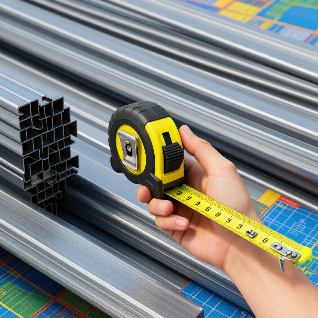
For large frames where a standard machinist square is too small, I rely on the Pythagorean theorem. By measuring 3 feet on one rail and 4 feet on the other, the diagonal between those two points must be exactly 5 feet. In a smaller workshop setting, you can use 3, 4, and 5 inches, but the larger the scale, the more accurate your verification will be.
Diagonal Measurement for Parallelograms
Even if your corners look square, a frame can still be a parallelogram. I always measure the diagonals from corner to corner. If the measurements are identical within 1/32 of an inch, the frame is square. If they differ, I know the structure has “racked” and needs adjustment before the stops are permanently welded down.
Designing Mechanical Stops and Clamping Features
Once your layout is verified, you need a way to hold the metal against your stops. Clamping is where many fabricators go wrong; they either use too much pressure and warp the fixture, or too little and the part moves during welding.
Using Fixed Locating Pins for Internal Alignment
If your workpiece has pre-drilled holes, locating pins are the gold standard for repeatability. I often use shoulder bolts or turned bar stock as pins. These pins should have a slight chamfer on the top to help guide the part into place. However, be careful with tolerances. If your pin is exactly the same size as the hole, the part might get stuck after the heat of welding causes it to shrink. I usually aim for a 0.010-inch clearance.
Integrating Hard Stops with Manual Clamping
Hard stops should be robust enough to handle the impact of a part being dropped into the fixture. I prefer to weld my stops on three sides, leaving the side facing the workpiece clean of weld fillets. This allows the workpiece to sit flush against the stop. For clamping, I use simple threaded “T-handle” bolts or toggle clamps. The key is to ensure the clamp pushes the part directly toward a stop, rather than into an open space where it could bend the metal.
- Place the part against the 3-point base.
- Slide it against the 2-point back wall.
- Bump it against the 1-point end stop.
- Apply clamping pressure directly over the support points to avoid bowing.
Managing Thermal Distortion and Shrinkage
Welding is a destructive process in terms of geometry. As the weld pool cools, it shrinks, pulling the surrounding metal toward the center of the bead. If you don’t account for this in your fixture design, you will find that you can’t get the finished part out of the jig.
Calculating Weld Shrinkage Allowances
A general rule of thumb I use is that a standard fillet weld will pull a joint inward by about 1/32 of an inch. If I am building a rectangular frame that needs to be exactly 24 inches wide, I might set my fixture stops at 24 and 1/32 inches to allow the metal to pull into the final dimension. This is a “learned” measurement that depends on your welding process and heat input.
Using Heat Sinks to Protect Fixture Accuracy
To keep my fixtures from warping over time, I integrate heat sinks. Large blocks of copper or thick aluminum placed near the weld zone can soak up excess heat, preventing it from reaching the structural members of the jig. If you don’t have copper, simply using a thicker steel base plate acts as a thermal mass, spreading the heat out and reducing localized distortion.
Verification Checklist for New Fabrication Tools
Before you start using your new fixture for a real project, you must run a “dry test.” I have a specific checklist I follow to ensure the tool is ready for service.
- Check for Burrs: Ensure all stops and pins are free of weld spatter or burrs that could offset the part.
- Verify Squareness: Re-measure diagonals after all stops are welded to ensure the welding of the jig itself didn’t pull it out of alignment.
- Test Loading/Unloading: Place a set of parts in the jig, clamp them, then unclamp and remove them. They should slide out without force.
- Check Clearance for Welding: Ensure your torch or gun can actually reach the joints while the part is in the fixture. I’ve built many jigs only to realize I blocked my own access to the weld.
- Thermal Expansion Gap: Ensure there is a small gap (around 1/16″) at the end of long runs to allow the metal to expand lengthwise without buckling.
Frequently Asked Questions
Why shouldn’t I just weld my stops directly to my welding table?
Welding stops to your primary table can warp the table surface over time. It is much better to build a “sub-plate” or a dedicated frame that can be clamped to the table. This keeps your main workspace flat and allows you to store the fixture for future use.
What is the best way to prevent the workpiece from sticking to the fixture?
I use a heavy coat of anti-spatter spray on the fixture itself, especially near the stops and pins. Additionally, I try to design my stops so they only touch the workpiece at small, specific points rather than along a long edge where a stray arc could “tack” the part to the jig.
How thick should my base plate be for a standard chassis jig?
For most automotive or furniture-scale projects, a 1/2-inch plate is the minimum I recommend. If you go thinner, the heat from the welding will eventually cause the plate to “potato chip,” or curl at the corners, which ruins your vertical accuracy.
Can I use wood or MDF for a welding jig?
I strongly advise against it for anything requiring precision. Wood changes size with humidity, and more importantly, it will char or catch fire. Even if it doesn’t burn, the heat from the weld will cause the wood to compress, meaning your second part won’t be the same as your first.
How do I account for the “pull” of a weld?
The best method is to “pre-set” your parts. If you know a weld will pull a vertical upright inward, you can shim the part so it leans slightly outward before welding. As the weld cools, it will pull the part into a perfectly 90-degree position.
Should I weld the entire fixture or just tack it?
You should fully weld the structural frame of the fixture but do so in stages to avoid warping the jig. For the locating stops, I prefer heavy tacks or short 1-inch beads. This makes it easier to move or “tune” the stops if you find your measurements are slightly off after a test run.
What is the 3-2-1 rule again?
It is a method to define a part’s position using six points of contact: three on the bottom (level), two on the side (alignment), and one on the end (stop). This prevents the part from moving in any direction while ensuring it is not over-constrained.
How do I check for squareness on a budget?
The 3-4-5 triangle method is the most accurate budget-friendly way. All you need is a reliable tape measure. For smaller parts, a high-quality 12-inch combination square is sufficient, provided you check it for accuracy against a known straight edge first.
Why is my fixture warping after only a few uses?
This usually happens because the fixture doesn’t have enough “mass” to handle the heat, or the welds on the fixture itself were too large and are now pulling the frame. Try using thicker material or adding gussets to the underside of your base plate to increase its rigidity.
How much clearance should I leave for locating pins?
I recommend a clearance of 0.010 to 0.015 inches. This is enough to allow for slight variations in the parts and thermal expansion, but tight enough to keep the part accurately positioned for most structural work.
(This article was written by one of our staff writers, James Harlan. Visit our Meet the Team page to learn more about the author and their expertise.)