How to Build Steel Stencil Templates for Repeat Cuts (Guide)
I remember the exact moment I realized my shop had outgrown its “hobbyist” roots. I was standing over a pile of twenty identical brackets, realizing that the fourteenth one was nearly an eighth of an inch off from the first. Despite my years of experience, manual measurement fatigue had set in. That afternoon, I stopped production and spent four hours building a permanent, hardened steel guide for that specific part. It was a turning point. Moving from manual layout to using durable metal patterns is the hallmark of a shop transitioning into professional-grade efficiency.
When you scale a fabrication business, the enemy isn’t just a lack of skill; it’s the accumulation of small, repeatable errors. Integrating robust steel guides into your workflow allows you to treat your manual and CNC stations as high-precision cells. This guide focuses on the physical engineering of these master patterns, the infrastructure required to produce them, and how to organize your shop floor to maximize their utility.
Mapping Material-Flow Loops for Template-Based Production
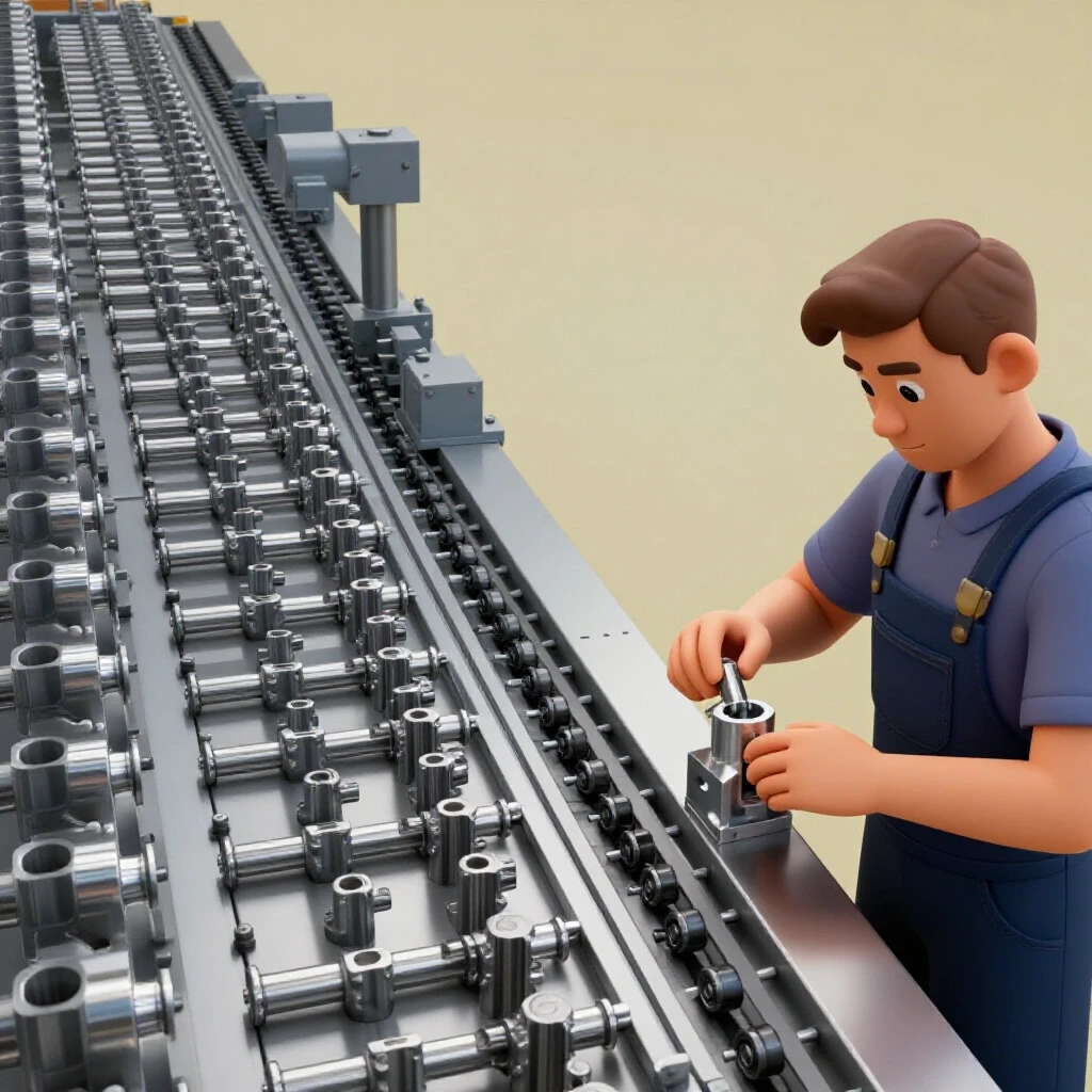
Material-flow mapping involves analyzing the physical path raw steel takes from the rack to the cutting station. By integrating durable metal guides into this path, you eliminate redundant measuring steps. This optimization reduces “travel waste” and ensures that every movement in the shop contributes directly to part completion.
In a lean manufacturing environment, we look at “spaghetti diagrams”—the lines representing where a person walks during a shift. If you have to walk from your cutting table to a tool chest for a square and then to a rack for a tape measure every time you start a cut, your layout is failing you. By creating a dedicated station for your steel patterns, you centralize the “intelligence” of the part.
Building on this, the goal is a linear flow. Raw stock enters at one end, moves to a template-guided cutting station, and then proceeds to finishing. This prevents the “bottleneck” effect where parts pile up because the operator is busy double-checking dimensions. Interestingly, a well-placed master pattern can reduce setup time by as much as 40% on repeat orders.
| Layout Type | Movement Pattern | Setup Time | Accuracy Consistency |
|---|---|---|---|
| Traditional Manual | Random/Circular | High (10-15 mins) | Variable |
| Template-Integrated | Linear/Direct | Low (2-3 mins) | High |
| Automated Cell | Fixed/Stationary | Minimal (1 min) | Absolute |
Evaluating Shop Infrastructure for Heavy-Duty Tooling Production
Before you can produce high-quality metal guides, your shop infrastructure must support the load of heavy cutting and precision finishing. This requires an assessment of your electrical capacity, floor stability, and air management systems. Without a stable foundation, the tools used to create your patterns will lack the necessary precision.
Optimizing 3-Phase Power Delivery for Fabrication
A 3-phase power converter is often necessary for advanced shop owners who need to run industrial-grade plasma cutters or mills used in template creation. These systems provide a more consistent voltage than single-phase power, which is critical for the smooth arcs and clean edges required for master patterns.
I transitioned to a rotary phase converter about ten years ago when my CNC gantry started losing steps during heavy loads. A rotary converter uses a “idler motor” to generate the third leg of power, providing a balanced voltage that protects your electronics. For a shop running a 50-amp plasma system and a 5-HP compressor simultaneously, a 20-HP rotary converter is a standard benchmark to ensure you don’t experience voltage drops that ruin a critical cut.
Designing High-Volume Clean Air Filtration
Air quality management is non-negotiable when cutting steel patterns, as the process generates fine metallic dust and hazardous fumes. A high-volume air scrubbing system must be capable of moving enough air to clear the “cloud” generated by high-heat cutting tools.
In my shop, I aim for a minimum of 1,000 to 2,000 CFM (Cubic Feet per Minute) at the source. This is achieved through a multi-stage cyclone dust collector and localized fume extraction. When designing your ductwork, remember that every 90-degree bend adds “static pressure loss,” which reduces the effective suction at the tool. Keeping duct runs short and using long-radius elbows ensures your air remains breathable and your equipment stays clean.
- CFM Requirement: 1,000–2,000 for plasma/grinding zones.
- Duct Diameter: 6-inch main lines to maintain air velocity.
- Static Pressure: Aim for less than 5 inches of water gauge loss.
Selecting and Preparing Steel Plate for Durable Workshop Guides
Choosing the right material for your master patterns is a balance between durability and ease of fabrication. While mild steel is common, the thickness and surface preparation determine how long the guide will remain accurate under the heat and friction of daily use.
I typically recommend 3/16-inch or 1/4-inch mild steel plate for most workshop patterns. This thickness provides enough “meat” for a torch or scribe to follow without the plate warping or shifting. Building on this, the surface must be stripped of mill scale before the layout begins. Mill scale is a hard, brittle oxide layer that can deflect a scribe or cause a plasma arc to sputter.
As a result of using thicker plate, you also gain the ability to “edge harden” the guide through repeated use, or simply rely on the mass of the steel to resist the heat of a hand-held plasma torch. If the guide is too thin, it will dissipate heat poorly, leading to thermal expansion that can throw your measurements off by several thousandths of an inch over a long cut.
Precision Layout and Profiling Techniques for Master Patterns
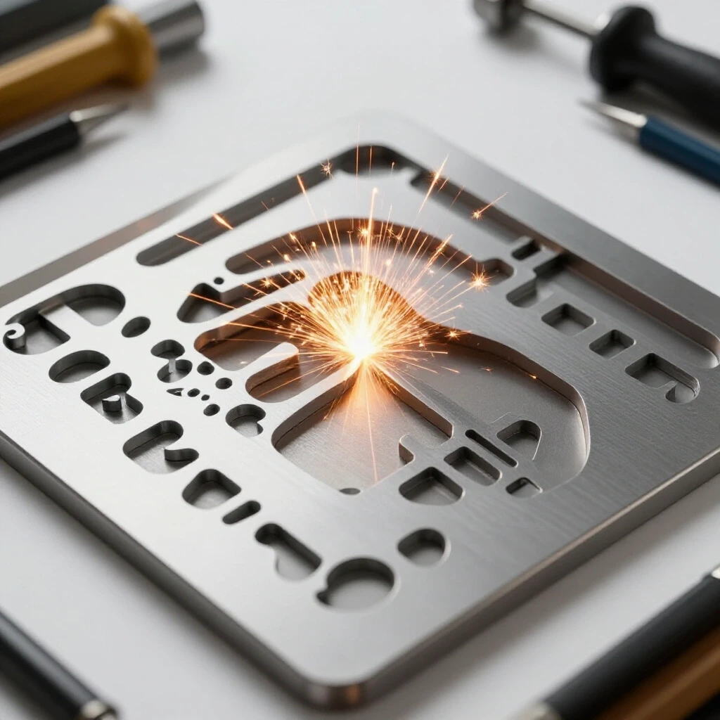
The accuracy of your final parts is entirely dependent on the precision of the initial layout on the master plate. This process involves technical scribing, controlled cutting, and meticulous edge finishing to ensure a smooth path for your cutting tools to follow.
Scribing and Manual Profiling
For shops without a CNC system, manual layout requires high-contrast marking and precision hand tools. I use a carbide-tipped scribe and a layout fluid like Dykem Blue to make my lines stand out. This allows for a “hairline” level of accuracy that is impossible to achieve with a standard soapstone or marker.
When cutting the profile, I always leave about 1/32 of an inch of “extra” material. This allows me to use a fine-tooth file or a flap disc to bring the edge perfectly to the line. This finishing step is crucial; any nick or bump in the edge of your steel guide will be mirrored in every single part you cut from it.
Integrating CNC Plasma for Pattern Creation
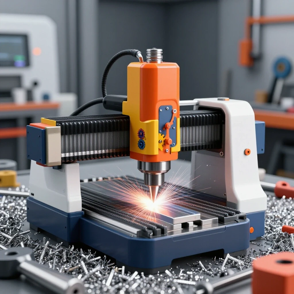
If you have integrated a CNC plasma table into your workflow, the process of building guides becomes much faster, but it requires careful calibration. You must account for “kerf compensation,” which is the width of the material removed by the plasma arc.
In my experience, a standard plasma kerf is around 0.040 to 0.060 inches. If you don’t adjust your toolpath to account for this, your master pattern will be undersized. I always run a test cut on a scrap piece of the same thickness to verify the exact kerf before committing to the final pattern. Once the CNC has finished the cut, the edges should still be checked with a machinist’s square to ensure no dross or beveling has occurred.
Fixturing and Alignment Features for Repeatable Accuracy
A steel guide is only useful if it can be positioned identically every time. Fixturing features like alignment holes, tabs, and clamping zones are what transform a simple piece of cut steel into a professional-grade manufacturing tool.
Building on this concept, I incorporate “index holes” into almost every pattern I make. These are small, precisely drilled holes that allow me to drop a pin through the guide and into a pre-drilled hole in the workpiece or the welding table. This eliminates the need for measuring from the edge of the material every time.
- Index Holes: 1/4-inch or 3/8-inch holes for alignment pins.
- Clamping Tabs: Extensions of the plate that allow for C-clamps without obstructing the cut path.
- Weight Relief: Large internal cutouts to make heavy patterns easier to handle without sacrificing rigidity.
Interestingly, adding a simple handle or a “hanging hole” to your patterns encourages shop staff to store them properly. A master guide that is bent or scratched because it was buried under a pile of scrap is no longer a precision tool.
Optimizing the Cutting Station for High-Volume Workflow
Once your steel patterns are built, the physical layout of the cutting station determines how much throughput you can achieve. This involves machine zoning, clear access paths, and the strategic placement of support equipment.
I follow a “three-foot rule” in my shop: there must be at least three feet of clear space around every major machine or cutting table. This ensures that the operator has room to maneuver large sheets of steel and can safely position the master guides without tripping over cords or scrap.
Building on this, the cutting station should be equipped with its own dedicated air supply and electrical drops. If you are using a 3-phase system, ensure the drops are balanced across the phases to prevent “voltage sag” when the compressor kicks in. A well-organized station, combined with durable steel patterns, allows a single operator to produce parts at a rate that would normally require a much larger team.
| Equipment | Electrical Load (Amps) | Air Requirement (PSI/CFM) | Floor Space (Sq. Ft.) |
|---|---|---|---|
| CNC Plasma Table | 40-60 (3-Phase) | 90 PSI / 6 CFM | 50-100 |
| Manual Cutting Station | 30-50 (Single) | 90 PSI / 5 CFM | 25-40 |
| Grinding/Finishing | 15-20 (Single) | N/A | 15-20 |
Maintaining and Cataloging Your Metal Master Collection
As your library of guides grows, so does the need for a systematic way to store and track them. A steel pattern is an asset, and like any asset, it requires maintenance and a clear “address” in the shop.
I use a simple alphanumeric stamping kit to label every guide with a part number. This number corresponds to a sheet in my shop manual that lists the material type, the required settings for the plasma cutter, and the estimated time for each cut. This level of documentation is what separates a “job shop” from a micro-manufacturer.
To prevent rust, I apply a light coat of dry lubricant or a specialized tool wax to the patterns. Unlike oil, these don’t attract grinding dust, which can act as an abrasive and wear down the edges of the guide over time. Every six months, I inspect the edges for “torch wash”—the gradual erosion caused by the heat of the plasma arc—and file them back to true if necessary.
Practical Steps for Scaling Your Shop Efficiency
Transitioning to a template-based workflow is a marathon, not a sprint. The goal is to build a system that supports growth without adding unmanageable complexity or cost.
- Identify High-Repeat Parts: Look at your sales data from the last six months. Any part you’ve made more than five times is a candidate for a steel guide.
- Audit Your Power: Ensure your 3-phase or high-amp single-phase circuits are stable. Use a multimeter to check for voltage drops during peak operation.
- Upgrade Air Filtration: Don’t wait for the shop to get smoky. Install a localized extraction arm at your primary cutting station.
- Standardize Your Material: Pick a standard thickness for your guides (like 1/4-inch) so you can use the same alignment pins and clamps for all of them.
- Build a Storage Rack: Dedicate a wall or a rolling cart to your master patterns. Keep them vertical to prevent warping.
By focusing on these foundational elements, you create a shop environment where “precision” is built into the floor plan and the tooling, rather than being a stressful variable that depends on the operator’s mood.
Frequently Asked Questions
What is the best steel thickness for a repeatable cutting guide?
For most manual and semi-automated fabrication, 3/16-inch or 1/4-inch mild steel is ideal. It is thick enough to resist warping from heat and provides a solid edge for a torch or scribe, yet it isn’t so heavy that it becomes difficult to maneuver on the workbench.
Why should I use a rotary phase converter instead of a static one for my CNC?
Rotary phase converters provide a true, balanced 3-phase signal that is much closer to utility power. Static converters often only provide a “boost” to start a motor and then drop back to two phases, which can cause electronics in CNC gantries to behave unpredictably or overheat.
How do I account for the width of the cut when making a steel pattern?
This is known as kerf compensation. You must measure the width of the gap created by your specific cutting tool (usually 0.040″ to 0.060″ for plasma) and add or subtract half of that value from the edge of your pattern, depending on whether it is an internal or external cut.
How much airflow do I really need for a plasma cutting station?
To maintain a safe and clean environment, you should aim for 1,000 to 2,000 CFM at the source. This ensures that the heavy metallic dust and fumes are captured before they can disperse into the rest of the shop or settle on your precision machinery.
Can I use mild steel for a guide that will be used with a handheld plasma torch?
Yes, mild steel is the standard choice. While the heat from the torch will eventually cause some wear (“torch wash”), a 1/4-inch plate will last for hundreds of cuts before needing to be dressed with a file.
What is the “three-foot rule” in shop layout?
The three-foot rule suggests maintaining a minimum of 36 inches of clear floor space around all machinery. This provides enough room for safe operation, material handling, and maintenance access, which is critical when moving heavy sheets of steel and large patterns.
How do I prevent my steel patterns from rusting without making them greasy?
Avoid using standard motor oil or WD-40, as they attract dust. Instead, use a dry silicone spray or a dedicated “tool wax.” These products create a protective barrier that prevents oxidation but remains dry to the touch.
Do I need to heat-treat the edges of my steel guides?
For the majority of shop applications, heat treating is unnecessary and can cause the plate to warp. Mild steel is naturally tough enough to handle scribes and plasma arcs. If you find an edge is wearing down, it is usually more cost-effective to file it true or cut a new guide.
How do I ensure my index holes are perfectly aligned?
The most reliable method is to drill the index holes in the master pattern using a drill press or CNC mill, then use that pattern as a “drill jig” for your workpieces. This ensures that the relationship between the holes and the cut edge remains identical across every part.
What is the most common mistake when building a master guide?
The most common mistake is failing to remove the mill scale from the steel plate before layout. Mill scale is uneven and can cause your scribe to jump or your plasma arc to deflect, leading to an inaccurate master pattern that ruins every part made from it.
(This article was written by one of our staff writers, Edward Sinclair. Visit our Meet the Team page to learn more about the author and their expertise.)