How to Calculate and Compensate for Weld Shrinkage (Guide)
I spent my first three years in a fabrication shop thinking that if I clamped a frame tight enough to the table, it would stay straight. I was wrong. I remember building a heavy-duty engine stand for a neighbor. I used thick-walled square tubing and laid down heavy, beautiful beads. When I finally released the clamps, the upright post didn’t just lean; it jumped. The heat had pulled the vertical member five degrees out of square. That was my first real lesson in how metal behaves like a living, breathing thing when you introduce the heat of an arc.
In my 14 years of inspecting industrial components and running my own shop, I have learned that you cannot fight physics. You have to work with it. When we melt steel, it expands. As it cools and turns back into a solid, it occupies less space than it did when it was molten. This contraction creates immense internal forces that can twist a project into a scrap pile. For those of us working in home shops or small garages, understanding these forces is the difference between a project that fits and one that fails.
The Mechanics of Metal Movement During the Cooling Phase
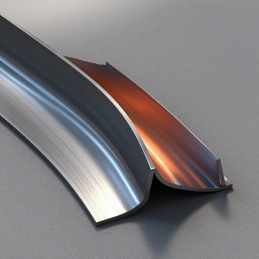
Thermal contraction is the physical reduction in volume that occurs as a weld pool cools from a liquid state to a solid, ambient temperature. This process creates internal tension that pulls the surrounding base metal toward the center of the weld, often resulting in visible warping or dimensional inaccuracy.
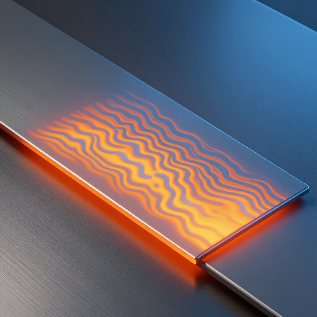
When you strike an arc, the temperature at the point of contact exceeds 3,000 degrees Fahrenheit. The metal in the Heat Affected Zone (HAZ) expands rapidly. However, because the cooler metal surrounding the joint resists this expansion, the hot metal “upsets” or thickens. As the weld cools, it tries to shrink back to its original size, but it is now constrained. This results in a permanent pull. Interestingly, most common steels will experience a linear reduction of about 1% to 3% depending on the volume of the weld.
To manage this, I always look at the weld volume first. A massive fillet weld where a small one would suffice is a recipe for disaster. The more filler metal you add, the more “pull” you generate. I once saw a structural base plate curl like a potato chip because the fabricator thought “more is better” and doubled the specified weld size. By keeping your weld profiles to the minimum required for the load, you reduce the total energy acting on the joint.
Determining Expected Dimensional Loss in Standard Joints
Predicting how much a joint will move requires analyzing the joint geometry and the amount of heat being applied to the metal. By using empirical data from test coupons, fabricators can estimate the shrinkage and adjust their initial measurements to ensure the final piece meets the required dimensions.
In my shop, I use a simple rule of thumb: for every inch of weld width, expect a specific amount of transverse pull. If you are working with 1/4-inch plate, a standard butt weld might pull the plates together by 1/16 of an inch. If you don’t account for this by gapping the plates slightly wider than the finished spec, your overall assembly will be too short.
| Joint Type | Typical Movement Direction | Estimated Shrinkage (Linear) |
|---|---|---|
| Butt Weld | Transverse (pulls together) | 1% to 2% of weld width |
| T-Joint (Fillet) | Angular (pulls toward weld) | 1 to 3 degrees per pass |
| Lap Joint | Longitudinal (shortens bar) | 0.5% of total weld length |
| Corner Joint | Angular (closes the angle) | 2 to 5 degrees |
Building on this data, I always suggest running a test coupon. Take two scraps of the same material, measure them precisely, weld them using your planned settings, and measure again. This “shop floor data” is more valuable than any textbook because it accounts for your specific welding machine and travel speed.
Restraint Strategies to Combat Positional Shifting
Fixture restraint involves using clamps, jigs, or temporary “strongbacks” to hold workpieces in a fixed position during the heating and cooling cycles. This method forces the internal stresses to manifest as internal tension rather than external distortion, though it requires careful timing when releasing the restraints.
Clamping is your first line of defense, but it is a double-edged sword. If you clamp a project too rigidly and leave it that way, you can actually cause the weld to crack because the metal cannot move at all. I prefer a “controlled restraint” approach. For example, when welding a long frame, I use heavy C-clamps and square blocks, but I also use tack welds that are large enough to hold the load but small enough to be ground out if I see the alignment shifting.
- Tack Welding: Place tacks in a mirrored sequence. If you tack the top right, tack the bottom left next.
- Strongbacks: Weld temporary bits of scrap across a joint to keep it flat, then cut them off after the piece has cooled to room temperature.
- Jigging: Use a flat, heavy steel table as a reference plane. A 1/2-inch thick table is a standard benchmark for garage fabrication safety.
Thermal Sequencing Techniques for Structural Stability
Welding sequences, such as back-stepping or skip welding, involve breaking a long continuous bead into smaller segments welded in a specific order. This distributes the heat more evenly across the structure, preventing the cumulative pull that occurs when welding in a single direction.
One of the biggest mistakes I see in intermediate shops is “the long run.” A builder starts at one end of a four-foot seam and drags the puddle all the way to the end. By the time they reach the finish, the heat build-up has expanded the plates so much that they overlap or veer off-track. Instead, I use the back-step method. I start three inches from the beginning and weld toward the start. Then I move another three inches forward and weld back to the previous bead.
This technique works because the shrinkage of the second bead is countered by the cooling of the first. It keeps the overall heat input lower and more localized. Another great tool is skip welding. If you are welding a box frame, weld the top left corner, then move to the bottom right. By the time you come back to the first corner, the metal has already moved through its primary cooling phase.
Workshop Safety Protocols for High-Heat Fabrication
Safe workshop protocols during high-heat operations include the use of appropriate personal protective equipment (PPE), ensuring adequate ventilation to manage fumes, and maintaining a clear “hot zone” to prevent fires. These steps protect the fabricator while they manage the physical stresses of the metal.
When you are focused on managing metal distortion, it is easy to forget that the heat you are fighting is a safety hazard. I always maintain a 15-20 CFH (cubic feet per hour) gas flow rate for MIG welding to ensure the arc is stable. A wandering arc adds unnecessary heat and increases the risk of warping. Your PPE should be non-negotiable. I use a Shade 10 to 13 auto-darkening helmet depending on the amperage.
- Workshop Safety Checklist:
- Clear all flammable liquids (gas cans, cleaners) at least 35 feet from the welding area.
- Wear leather sleeves or a full jacket; heat-affected metal stays “burn-hot” long after the glow disappears.
- Use a dedicated cooling rack for finished parts so you don’t accidentally touch a hot workpiece.
- Check your fire extinguisher gauge every time you start the welder.
Pre-bending and Offsetting for Alignment
Pre-bending is a proactive technique where a fabricator intentionally offsets or bends a part in the opposite direction of the expected weld pull. When the weld cools, the resulting shrinkage pulls the part back into the desired “zero” or square position.
This is where the “art” of fabrication meets the science. If I know a T-joint is going to pull a vertical post inward by two degrees, I will clamp it so it leans two degrees outward before I start. It feels wrong while you are doing it. You look at the part and think, “That’s crooked.” But as the weld cools, you can actually watch the post slowly pull itself into a perfect 90-degree angle.
I once worked on a set of heavy gate hinges. If I had welded them flat, the weight of the gate would have caused them to bind. By offsetting the hinge pins by just 1/16 of an inch to account for the weld pull, the gate swung perfectly on the first try. Always remember: you aren’t building for how it looks now; you are building for how it will look after it cools.
Correcting Distortion After the Arc Stops
Post-weld correction involves using mechanical force or localized heat to return a warped component to its intended shape. While prevention is preferred, these methods allow a fabricator to salvage a project that has shifted during the welding process.
Sometimes, despite our best efforts, the metal moves more than we expected. If a frame has a slight bow, you can often fix it with a “flame shrink.” Using an oxy-acetylene torch, you heat a small, wedge-shaped area on the side opposite the weld pull. When that spot cools, it shrinks, pulling the metal back the other way. This should be done sparingly, as repeated heating can weaken the Heat Affected Zone and reduce the structural metal load capacity.
Mechanical straightening is another option. I keep a 20-ton hydraulic shop press specifically for this. If a flat bar has a slight “camber” after welding, a few carefully placed pumps on the press can bring it back to true. However, always check for cracks after straightening. Cold-working a weld can introduce brittle fracture points if you are too aggressive.
Monitoring Heat Input and Gas Flow
Controlling the energy delivered to a joint is a primary factor in minimizing dimensional changes. Proper gas flow rates and voltage settings ensure a stable arc, which allows for faster travel speeds and a narrower heat-affected zone.
| Parameter | Recommended Range | Effect on Distortion |
|---|---|---|
| Shielding Gas Flow | 15–20 CFH | Stabilizes arc; prevents excess heat from “searching” |
| Travel Speed | 10–20 inches per minute | Faster speeds reduce the total heat-affected zone |
| Wire Feed Speed | Per manufacturer chart | Higher speeds increase deposition but also heat |
| Voltage | Minimum for penetration | Lower voltage keeps the puddle small and manageable |
I use an electronic gas flow regulator to ensure I’m not wasting gas or creating turbulence. If your gas flow is too high, it can actually pull oxygen into the weld, causing porosity. Porosity doesn’t just weaken the weld; it makes the joint more prone to cracking under the stress of thermal contraction.
Practical Steps for a Successful Build
- Analyze the Load Path: Determine which joints are structural and which are cosmetic. Prioritize the structural joints for heavy clamping.
- Clean Your Material: Mill scale and rust act as insulators, forcing you to turn up the heat. Clean metal welds faster and cooler.
- Set the Gap: Use a feeler gauge or a piece of TIG rod to set consistent gaps in butt joints. This allows the metal to shrink into the gap rather than overlapping.
- Tack Heavily: For a 24-inch seam, I use 1/2-inch tacks every 4 inches.
- Weld in Segments: Never weld more than 6 inches at a time without letting the metal “rest” or moving to a different part of the project.
- Measure Constantly: Check your square and your dimensions after every three or four tacks. It is easier to fix a tack than a full bead.
- Let it Cool Naturally: Never quench a structural weld in water. Forced cooling can make the steel brittle and increase internal stress.
FAQ: Managing Metal Movement and Workshop Safety
How much should I gap my plates to account for shrinkage?
For most workshop projects using 1/8-inch to 1/4-inch steel, a gap of about 1/16 of an inch is a safe starting point. This provides space for the weld metal to contract without pulling the plates over each other. If you are doing a full-penetration butt weld, the gap should be roughly equal to the thickness of your welding wire.
Can I stop all warping if I use enough clamps?
No. You cannot stop the metal from wanting to shrink. If you clamp it too tightly, the force will simply stay internal. When you release the clamps, the part will either “spring” to a warped shape or, in worse cases, the weld itself will crack. The goal is to use clamps to guide the movement, not to eliminate it entirely.
Why does my metal always pull toward the side I am welding?
This is called angular distortion. The top of the weld pool is wider than the bottom. As that larger volume of liquid metal cools, it shrinks more than the root of the weld, creating a “hinge” effect that pulls the plates toward the face of the weld.
Is it better to weld fast or slow to prevent warping?
Faster travel speeds are generally better. Welding slowly allows heat to soak deep into the surrounding base metal, creating a larger heat-affected zone. A larger HAZ means more metal is expanding and contracting, which leads to more significant distortion.
How do I know if my weld has internal defects from shrinkage?
While professional shops use X-rays, you can look for “crater cracks” at the end of your welds. These often form because the cooling metal pulls apart as it solidifies. Always “back-fill” your craters by pausing for a second at the end of the bead to add a little extra filler metal.
What is the 1-3% rule in welding?
This rule suggests that the volume of the weld bead will shrink by approximately 1% to 3% in all directions as it cools. For a long 10-foot weld, this can mean a loss of nearly 1/4 inch in total length if not accounted for through sequencing or gapping.
Does the type of welder (MIG vs. TIG) affect shrinkage?
Yes. TIG welding generally introduces more total heat into the part because the travel speed is slower. MIG welding is often preferred for large frames because it is faster and keeps the heat more localized, resulting in less overall warping.
Should I pre-heat my metal to stop it from warping?
Pre-heating is usually used to prevent cracking in thick sections (over 1/2 inch) rather than to stop warping. In fact, pre-heating the entire part can sometimes make warping worse because the entire piece is expanding. For most garage projects, keeping the base metal at room temperature is sufficient.
How can I tell if a joint is under too much stress?
Listen to your project. If you hear a loud “ping” or “crack” sound as the metal cools, that is the sound of a weld or the base metal failing under internal tension. You should also look for “stress lines” in the mill scale near the weld, which indicate the metal is being pulled near its yield point.
What is a safety factor in fabrication?
A safety factor (like 2:1 or 4:1) means you design the joint to hold two to four times the expected load. This accounts for minor errors in welding or small amounts of internal stress caused by shrinkage. For any overhead or load-bearing structure, a 4:1 safety factor is a common industry benchmark.
Can I use a hammer to straighten warped metal?
Yes, this is called “peening.” By striking the weld bead with a ball-peen hammer while it is still slightly warm, you can actually stretch the metal back out. This counteracts the shrinkage. However, do this carefully, as over-peening can make the weld brittle.
What is the most important tool for managing shrinkage?
The most important tool is your tape measure and a high-quality square. By measuring before, during, and after welding, you create a feedback loop that teaches you exactly how much your specific setup pulls the metal. Over time, this data becomes your best guide for future projects.
(This article was written by one of our staff writers, James Harlan. Visit our Meet the Team page to learn more about the author and their expertise.)