How to Calibrate CNC Plasma Gantry Alignment (DIY Tutorial)
I have spent the better part of two decades standing over machines that refuse to behave. There is a specific kind of frustration that sets in when you finish a long cut, pull the part off the slats, and realize your 12-inch square is actually a trapezoid. You check your software, you check your file, and everything looks perfect. But the metal doesn’t lie. When the physical geometry of your machine is off, no amount of digital compensation can truly fix the underlying mechanical flaw.
In my 15 years as a diagnostic specialist, I have learned that most fabrication errors are not “ghosts in the machine.” They are usually the result of a systematic failure to maintain physical alignment. Whether it is a bridge that has “crabbed” sideways or a rail that has settled over time, these issues create a ripple effect. They lead to tool chatter, poor edge quality, and parts that simply do not fit together during assembly.
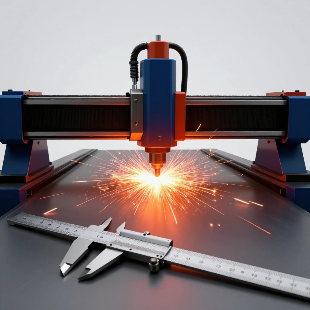
This guide is about returning to the basics of millwright work. We are going to look at how to identify, measure, and correct the physical orientation of a moving gantry system. We will use simple hand tools and a methodical approach to ensure your machine moves exactly how the controller thinks it is moving.
Establishing a Diagnostic Baseline for Machine Geometry
A diagnostic baseline is the known-good state of your machine’s physical frame. It involves verifying that the foundation is level and the primary rails are parallel before attempting to adjust the moving components. Without this baseline, any adjustments you make to the gantry will be built on a crooked foundation.
I once worked on a 5×10 foot table in a shop that had a slightly sloped concrete floor. The owner kept trying to square his gantry, but every time the machine moved to the far end of the table, the cuts went out of square again. We discovered that the weight of the gantry was causing the frame to twist because the leveling feet weren’t properly supporting the load. We had to start from the floor up.
Before touching the gantry, you must ensure your long-axis rails are parallel within 0.005 inches over their entire length. If one rail “dives” or “climbs” relative to the other, the gantry will tilt, creating a vertical misalignment that ruins your torch height control accuracy.
- Check the level of the main rails using a precision spirit level or a digital inclinometer.
- Verify rail parallelism by measuring the distance between rails at both ends and the middle using a calibrated tape or a tramming bar.
- Ensure all frame bolts are torqued to spec; a single loose gusset plate can allow the frame to shift under the inertial forces of high-speed direction changes.
Measuring Transverse Squareness with Precision Hand Tools
Transverse squareness refers to the 90-degree relationship between the long axis (X) and the cross-bridge (Y). This measurement ensures that perpendicular cuts are actually perpendicular, preventing “parallelogram” shapes in finished parts. If this is off by even a fraction of a degree, your bolt holes won’t line up and your tabs won’t fit their slots.
The most reliable way to check this is the “Large Triangle” method, often called the 3-4-5 rule. However, in a shop environment, we need more precision than a standard tape measure provides. I prefer using a machinist square and a dial indicator to sweep the gantry.
- Place a large, high-quality machinist square on the table, aligned perfectly with one of the long-axis rails.
- Mount a dial indicator to the torch carriage.
- Slowly move the carriage along the cross-bridge (Y-axis) while the indicator tip rides against the edge of the square.
- Note the deviation. If the indicator moves 0.010 inches over a 12-inch span, your gantry is significantly out of square.
| Error Type | Symptom | Diagnostic Tool |
|---|---|---|
| Parallelogramming | Rectangles have unequal diagonals | Large Square / 3-4-5 Test |
| Crabbing | Gantry judders or binds during travel | Caliper / Tape Measure |
| Vertical Tilt | Beveled edges on one side of the cut | Machinist Level / Plumb Bob |
| Backlash | Rounded corners or “ears” on starts | Dial Indicator |
Identifying and Correcting Gantry Rack and Pinion Sync
Synchronization in dual-drive systems ensures that both motors or drive linkages move the gantry ends at the exact same rate. When one side leads or lags, the bridge cocks at an angle, ruining accuracy. This is a common issue in machines that use independent motors for each side of the long axis.
In my experience, “crabbing” often happens after a minor collision or a power dip that causes one motor to skip a step. To fix this mechanically, you need to establish a physical “zero” point for both sides of the gantry.
I recommend using mechanical hard stops. Move the gantry manually (with the motors disengaged or powered down) until both sides are firmly pressed against the back of the frame. If the frame itself is square, this “homes” the gantry mechanically.
- Measure the distance from the gantry end-plate to a fixed point on the rail on both sides.
- If the measurements differ, loosen the drive coupling on the “lagging” side.
- Physically shift that side of the gantry until the measurements match within 0.002 inches.
- Re-tighten the coupling and perform a test move to see if the error returns.
The Role of Shimming in Resolving Vertical Plane Twist
Vertical plane twist occurs when one rail is higher than the other or when the gantry uprights are not plumb. Shimming involves placing thin metal strips under mounting points to bring components into a single flat plane. This is often the “hidden” cause of tool chatter and inconsistent cut quality.
If your gantry bridge is twisted, the torch will change its angle relative to the plate as it moves across the table. This results in a variable bevel that is impossible to tune out with gas settings. To diagnose this, I use a “sweep” test.
Mount a dial indicator to the torch holder and sweep it across a known-flat surface, like a piece of cold-rolled steel shimmed to be level with the rails. If the indicator fluctuates more than 0.005 inches over a 24-inch span, you likely have a twist in the bridge or an unlevel rail.
- Identify the low corner of the gantry mounting plate.
- Use steel shim stock (available in thicknesses from 0.001 to 0.015 inches).
- Loosen the mounting bolts just enough to slide the shim in.
- Re-torque and re-measure. This is an iterative process; don’t expect to get it on the first try.
Systematic Troubleshooting of Mechanical Vibrations and Backlash
Backlash is the “slop” or play between driving and driven components, such as a gear and a rack. Excessive backlash causes tool chatter and rounded corners, which often mimic alignment issues but require different fixes. If your gantry is square but your parts still look “wavy,” backlash is your primary suspect.
To measure backlash, I use a dial indicator pushed against the gantry. With the motors locked (powered on), try to physically push the gantry back and forth. The amount the indicator needle moves is your mechanical backlash.
In a well-maintained machine, you want to see less than 0.003 inches of play. If you see 0.010 inches or more, your pinion gears are likely worn, or the spring tensioner that holds the motor against the rack has weakened.
- Inspect the teeth of the rack for debris or metal shavings; these cause “phantom” vibrations.
- Check the pinion gear for a “hooked” tooth profile, which indicates it needs replacement.
- Ensure the motor mounting bolts haven’t vibrated loose. I’ve seen cases where a “vibration issue” was just a motor hanging by two loose bolts.
Case Study: The 0.040-Inch Ghost
I once consulted for a shop that was ready to scrap a three-year-old machine. They were getting a 0.040-inch error over a 20-inch cut. They had replaced motors and cables, thinking it was an electrical “glitch.”
We started by stripping the gantry down to the bearings. Using a precision straightedge, we found that the left-side rail had a slight bow in the middle. Because the gantry was rigidly bolted, that bow was forcing the entire bridge to pivot every time it passed the center of the table.
The fix wasn’t a new motor; it was loosening the rail mounting bolts, using a string line to pull the rail straight, and re-torquing the bolts. We spent four hours on mechanical alignment and the error dropped to 0.002 inches. The lesson here is that you cannot fix a bent rail with a software offset.
Mechanical Alignment Checklist
Use this checklist every 500 hours of machine operation or after any “torch crash.”
- Frame Level: Verify the four corners of the table are level within 0.005 inches.
- Rail Parallelism: Measure rail-to-rail distance at three points. Tolerance: +/- 0.005 inches.
- Gantry Squareness: Use the 3-4-5 method or a machinist square. Target: < 0.005 inches deviation over 12 inches.
- Pinion Engagement: Ensure the pinion is fully seated in the rack with no visible daylight between teeth.
- Bearing Pre-load: Check that V-guide wheels or linear blocks have no “rocking” motion.
- Fastener Integrity: Mark bolt heads with a paint pen to easily spot if they have vibrated loose.
Why Tool Chatter and Vibration Often Point to Alignment
When we talk about tool chatter, we are usually talking about resonant harmonics. If a gantry is not square, the bearings on one side might be under more tension than the other. This uneven loading creates a “tuning fork” effect. As the machine moves, it vibrates at a specific frequency, leaving a “washboard” pattern on the edge of your cut.
I always tell fabricators: “If it sounds wrong, it is wrong.” A machine in perfect alignment should move with a consistent, low-frequency hum. If you hear high-pitched chirping or a rhythmic thumping, your gantry is likely fighting itself.
- Check for “flat spots” on drive rollers or bearings.
- Ensure the gantry bridge is not “ringing” by adding mass or checking the tightness of all cross-members.
- Verify that the torch lead cables are not pulling on the carriage, which can introduce a bias to one side.
Closing the Loop on Precision
Achieving a perfectly square machine is not a “one and done” task. Metal moves. Floors settle. Bolts stretch. The most successful shops I’ve worked with treat mechanical calibration as a routine maintenance task, not a repair.
By using systematic measurement—moving from the floor to the rails, then the gantry, and finally the torch carriage—you isolate variables. You stop guessing and start knowing. When you know your machine is mechanically sound, you can cut with the confidence that the part coming off the table will match the drawing in your hand.
Frequently Asked Questions
Why does my gantry stay square at the home position but go out of square at the far end of the table?
This almost always indicates that your long-axis rails are not parallel. If the rails diverge (get wider) or converge (get narrower) as the gantry moves, the bridge is forced to “cock” to accommodate the change in width. Measure the distance between your rails at both ends of the table with a precision tape or tramming bar. They should be within 0.005 inches of each other.
How often should I check the squareness of my machine?
I recommend a quick check once a month for hobbyist use, and once a week for high-production environments. Additionally, you should perform a full calibration after any significant “crash” where the torch hits a tipped-up part, as the inertia can easily skip a tooth on a drive belt or rack.
Can I use a standard carpenter’s square for this process?
No. Standard framing or carpenter squares are not manufactured to the tolerances required for CNC machinery. A 12-inch machinist square (Grade B or better) is a necessary investment. A carpenter’s square can be off by as much as 0.030 inches over its length, which is more than the error you are trying to fix.
What is the 3-4-5 method, and how do I use it on a CNC?
The 3-4-5 method uses the Pythagorean theorem (a² + b² = c²) to create a perfect 90-degree angle. You mark a point 3 feet (or 30cm) along one axis and 4 feet (or 40cm) along the other. The diagonal distance between those two points must be exactly 5 feet (or 50cm). For a CNC, you can program the machine to move to these coordinates and check the physical distance with a tape measure.
My gantry is square, but I still get beveled cuts. What else could it be?
If the gantry is square to the rails but you still see a bevel, the torch itself may not be “plumb” (perfectly vertical) to the slats. Use a small square to check the torch body against the table surface in both the X and Y directions. Also, check if your slats are level; if the plate is sitting at an angle, the cut will be beveled even if the machine is perfect.
What is “crabbing,” and how do I identify it?
“Crabbing” is when one side of the gantry leads the other, causing the bridge to travel at an angle. You can identify this by measuring from the gantry end-plate to the end of the rail on both sides while the machine is at the “home” position. If the measurements aren’t identical, the gantry is crabbing.
Do I need to worry about temperature changes in my shop?
Yes. Large steel frames expand and contract with temperature. If you calibrate your machine in a 50-degree shop in the morning and it heats up to 90 degrees by the afternoon, the rails can expand at different rates if one is in the sun and the other is in the shade. Try to calibrate at a “median” temperature that reflects your typical working conditions.
What should I use for shimming?
Always use metal shim stock. Avoid using paper, plastic, or wood, as these materials compress over time or absorb moisture, which will ruin your alignment. Steel or brass shim kits are inexpensive and allow you to make adjustments as small as 0.001 inches.
How do I know if my drive belts are the cause of misalignment?
If your machine uses belts, uneven tension is a common culprit. If the belt on the left side is tighter than the belt on the right, the tighter side will respond faster to motor movements, causing the gantry to “whip” or go out of square during rapid accelerations. Use a tension gauge to ensure both belts are tuned to the same frequency or deflection.
Can a loose bearing cause a squareness error?
Absolutely. If the V-guide wheels or linear bearings on one side of the gantry have “play,” that side can lag or shift during a cut. You should not be able to “wiggle” the gantry by hand. If you can, tighten the eccentric nuts on your rollers or check your linear blocks for wear.
(This article was written by one of our staff writers, Paul Whitaker. Visit our Meet the Team page to learn more about the author and their expertise.)