How to Identify and Prevent Metal Lathe Tool Wear (Guide)
I have spent the better part of two decades standing on concrete floors, listening to the distinct hum of machinery. When a shop is running well, there is a certain rhythm to it. But when that rhythm breaks—when a finish comes off the lathe looking like a plowed field or a tool bit snaps for no apparent reason—the frustration is immediate. I have been there, staring at a ruined piece of 4140 steel, wondering which variable in the system failed me.
In my 18 years as a millwright and diagnostic specialist, I have learned that mechanical failures are rarely random. They are the result of specific, traceable causes. Whether I am tracking down the source of welding porosity in a structural frame or isolating the harmonic vibrations that lead to premature edge failure on a manual lathe, the process is the same. It requires a systematic approach, moving from the most obvious mechanical baselines to the subtle metallurgical interactions at the cutting edge.
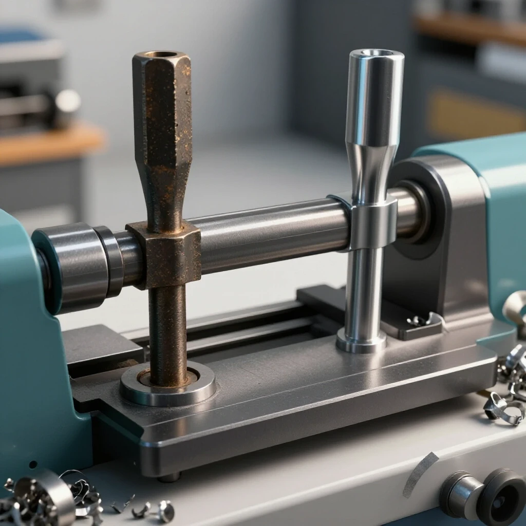
This guide is designed to help you move past guesswork. We will break down how to observe the physical signs of tool degradation, how to isolate machine-side issues like spindle backlash, and how to adjust your workflow to ensure your equipment performs reliably.
Establishing a Systematic Metalworking Diagnostic Guide
A systematic diagnostic guide is a structured framework used to isolate variables and identify the root cause of equipment or process failure. By moving from external observations to internal mechanical checks, a fabricator can eliminate “noise” and focus on the specific factor—be it heat, vibration, or alignment—causing the issue.
When a tool fails prematurely, my first step is always to stop and observe. I look at the chip color, the surface finish of the workpiece, and the state of the cutting edge under magnification. In my experience, most shop problems are solved by the “Rule of One.” You change exactly one variable—perhaps the spindle speed or the tool height—and observe the result. If you change three things at once and the problem disappears, you still do not know what the problem was. You have merely delayed its return.
To begin a proper diagnosis, you must establish a baseline. This involves checking that the machine is physically capable of performing the task. Is the lathe leveled? Is the tool on center? Is the work held rigidly? Only after confirming these mechanical constants can we look at the interaction between the tool and the material.
Recognizing Physical Indicators of Cutting Edge Degradation
Recognizing physical indicators of cutting edge degradation involves identifying specific patterns of wear, such as flank abrasion or cratering, on the tool surface. Understanding these visual cues allows a machinist to determine if the failure was caused by excessive heat, incorrect cutting speeds, or mechanical instability during the turning process.
Flank Wear and Abrasive Friction
Flank wear is the most common form of degradation I see in manual turning. It appears as a flat, abraded land on the side of the tool that rubs against the finished workpiece. This is typically a result of simple friction. If the flank wear exceeds 0.015 to 0.030 inches, the tool will begin to generate excessive heat, leading to a breakdown of the material’s hardness.
When I diagnose flank wear, I look at the spindle speed (RPM). If the speed is too high for the material’s surface feet per minute (SFM) rating, the friction becomes unsustainable. In one case involving a large batch of cold-rolled steel, we reduced the RPM by 15% and saw the tool life double. It is a balance of productivity versus tool longevity.
Crater Wear and Chemical Interaction
Crater wear occurs on the top face of the tool where the chip slides across the surface. It looks like a small “valley” or pit just behind the cutting edge. This is often caused by a chemical reaction or intense heat at the interface where the chip is formed. If the crater becomes too deep, it weakens the cutting edge until it eventually breaks off.
This often happens when cutting tougher alloys like stainless steel. The heat doesn’t dissipate into the chip quickly enough, and instead, it migrates into the tool. I often find that increasing the feed rate—which creates a thicker chip to carry away more heat—can actually reduce cratering, provided the machine has the rigidity to handle the load.
Built-Up Edge (BUE) and Material Adhesion
Built-up edge is a frustrating phenomenon where bits of the workpiece material weld themselves to the tool tip. It creates a false cutting edge that is blunt and irregular. This results in a terrible surface finish and can cause the tool to “dig in” and shatter.
I usually see BUE when the cutting speed is too low or when the material is particularly “gummy,” like soft aluminum or low-carbon steel. The solution is often counterintuitive: you need to speed up. Increasing the SFM raises the temperature just enough to keep the material from sticking to the tool, allowing it to flow over the rake face as intended.
| Wear Type | Visual Indicator | Primary Cause | Immediate Fix |
|---|---|---|---|
| Flank Wear | Flat spot on the side | High cutting speed | Reduce RPM |
| Crater Wear | Pit on the top face | Excessive heat/speed | Increase feed or reduce RPM |
| Built-Up Edge | Metal stuck to tip | Low cutting speed | Increase RPM or use lubricant |
| Chipping | Missing chunks of edge | Vibration or shock | Check rigidity/reduce overhang |
Why Machining Chatter Ruins Tools—And How to Isolate Rigid Harmonic Vibrations
Machining chatter is a resonant vibration that occurs when the cutting forces fluctuate rapidly, causing the tool to bounce against the workpiece. These harmonics create a distinctive “screaming” sound and leave a wavy pattern on the metal, which rapidly destroys the sharp edge of any cutting tool.
Vibration is the silent killer of tool life. In my 18 years, I’ve seen more tools destroyed by poor rigidity than by incorrect speeds and feeds combined. Chatter isn’t just an annoyance; it’s a sign that your system has lost its “loop of rigidity.” This loop includes the spindle, the chuck, the workpiece, the tool post, and the lathe bed itself.
Identifying Spindle Backlash and Bearing Play
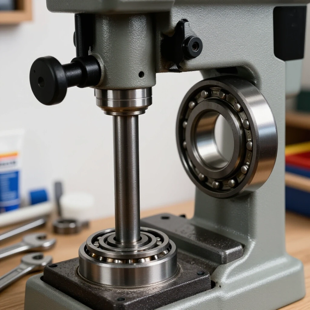
If you are struggling with tool chatter solutions, you must start at the spindle. I use a dial indicator to check for radial and axial play. Place the indicator tip on the spindle nose and apply firm hand pressure. If you see more than 0.001 to 0.002 inches of movement, your bearings may be worn or need adjustment.
I once spent three hours chasing a finish issue on a vintage engine lathe. I changed the tool geometry, the speed, and the feed, but nothing worked. Finally, I put a 12-inch pry bar in the chuck and gave it a gentle tug while watching the dial indicator. The spindle jumped 0.005 inches. The bearings were loose. Once we tightened the preload, the chatter vanished, and the tool life returned to normal.
Dampening Tool Overhang and Carriage Instability
The further a tool sticks out from the tool post, the more it acts like a tuning fork. I follow the “rule of thumb” that tool overhang should never exceed 1.5 to 2 times the thickness of the tool shank. If you have a 0.5-inch tool, it shouldn’t stick out more than 0.75 inches.
Check your carriage and cross-slide for backlash as well. If the gibs are loose, the cutting force will push the tool away, then the tool will “snap” back into the cut once the pressure builds up. This cycle repeats hundreds of times per second, creating the chatter we hear. Adjusting your gibs to a tolerance of 0.002 inches of play is a standard mechanical troubleshooting step that pays dividends in tool longevity.
Optimizing Cutting Parameters for Extended Tool Life
Optimizing cutting parameters involves calculating the ideal spindle speed, feed rate, and depth of cut based on the material properties and tool composition. By staying within the recommended technical limits, a fabricator can minimize thermal stress and mechanical shock, thereby preventing premature failure of the cutting edge.
The Math of Metal Removal
To prevent premature wear, you must understand Surface Feet Per Minute (SFM). This is the speed at which the metal moves past the tool. If you are turning a 2-inch bar of mild steel, your RPM should be significantly lower than if you were turning a 0.5-inch bar of the same material.
The formula is simple: RPM = (SFM x 4) / Diameter.
If you ignore this math, you are guessing. I have seen many intermediate fabricators run their lathes at the same speed for every job. This is a recipe for toasted tools. For example, high-speed steel (HSS) tools usually require an SFM of 60-100 for mild steel, while carbide can handle 300-600. Using carbide speeds on an HSS bit will turn the tip blue and soft in seconds.
Feed Rates and Depth of Cut
Feed rate—measured in inches per revolution (IPR)—determines how much metal the tool removes in one turn. If the feed is too light, the tool “rubs” rather than “cuts,” which generates immense heat and causes rapid flank wear. If the feed is too heavy, the mechanical pressure will chip the edge.
For most general turning on a manual lathe, I aim for a feed rate between 0.005 and 0.015 IPR.
- Light Finishing: 0.002 – 0.005 IPR
- General Turning: 0.007 – 0.012 IPR
- Heavy Roughing: 0.015+ IPR (depending on machine HP)
Correcting Lathe Alignment to Prevent Uneven Tool Loading
Correcting lathe alignment involves ensuring the spindle axis, the bed ways, and the tailstock are perfectly parallel and co-axial. Misalignment causes the tool to experience varying pressures as it moves along the workpiece, leading to tapered parts and localized wear on the tool’s nose radius.
The Two-Collar Test for Parallelism
If your lathe isn’t cutting straight, your tool is working harder than it needs to. I use the “two-collar test” to check alignment. Take a piece of scrap bar stock (at least 1.5 inches thick) and turn two small sections (collars) about 6 inches apart without moving the cross-slide.
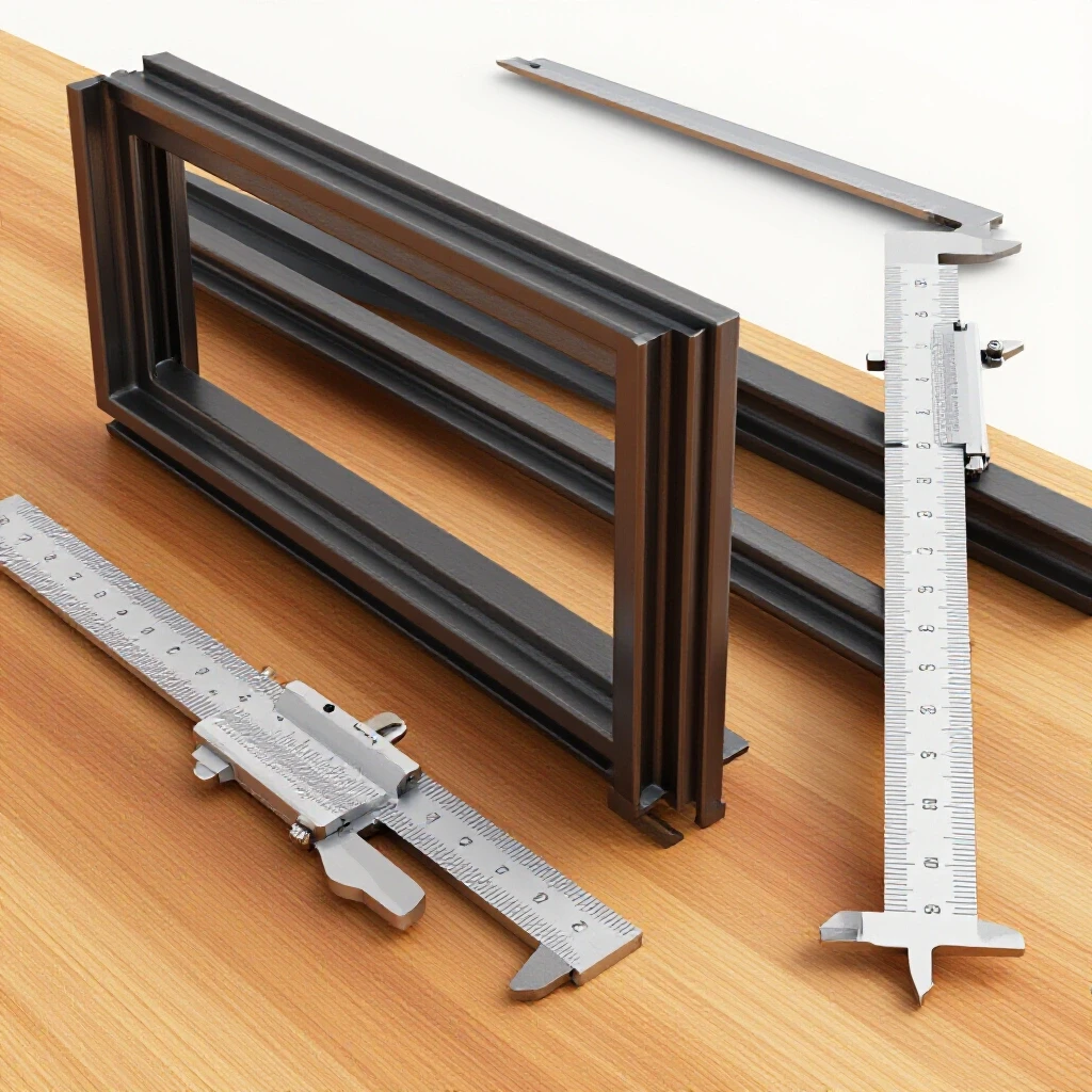
Measure both collars with a micrometer. If they differ by more than 0.001 inches, your headstock or bed is out of alignment. This misalignment forces the tool to take an increasingly deep or shallow cut as it travels, which can lead to unexpected tool failure or “dig-ins” near the chuck.
Tailstock Offsets and Center Alignment
When turning between centers, the tailstock must be perfectly aligned with the headstock. If it is offset, you will produce a taper. More importantly, it puts side-load on the tool. I check this by bringing the tailstock center up to a center held in the headstock and looking at them under a magnifying glass.
For precision work, I use a “test bar” between centers and a dial indicator on the carriage. This allows me to see exactly how much the tailstock needs to be adjusted. A tailstock that is out of alignment by even 0.005 inches over a 10-inch span can cause significant tool pressure issues.
Case Study: The 304 Stainless Steel Nightmare
I recall a project involving the fabrication of several custom shafts made from 304 stainless steel. The operator was going through HSS bits every ten minutes. He was frustrated, complaining about “bad steel.”
When I arrived, I performed a quick diagnostic check. First, I looked at the chips. They were straw-colored and very thin. This told me the tool was rubbing. Second, I checked the spindle speed. He was running at 400 RPM on a 1.5-inch bar.
The Diagnosis: Stainless steel work-hardens instantly if you rub it. By running too fast with a light feed, the tool was essentially trying to cut through a layer of hardened steel it had just created.
The Fix: 1. We swapped the HSS for a cobalt-steel tool bit for better heat resistance. 2. We dropped the speed to 150 RPM (approx. 60 SFM). 3. We increased the feed to 0.010 IPR to ensure the tool stayed “under” the work-hardened layer. 4. We used a heavy sulfur-based cutting oil.
The result? One tool bit lasted for the rest of the day. This wasn’t a “magic fix”; it was a systematic adjustment based on metallurgical reality.
Actionable Tracking Frameworks and Maintenance Checklists
To maintain a high-functioning shop, you need more than just a good eye; you need a record of what works. I recommend keeping a small logbook by each machine. When you find a speed and feed that produces a perfect finish on a specific material, write it down.
Lathe Alignment Checklist
- Leveling: Use a precision machinist’s level (0.0005″/ft) on the bed ways.
- Spindle Runout: Check the internal taper and the chuck face. Limit: 0.0005 inches.
- Tailstock Alignment: Use the two-collar test or test bar. Limit: 0.001 inches over 6 inches.
- Cross-Slide Gibs: Tighten until there is slight resistance, then back off 1/8 turn.
- Tool Post Rigidity: Ensure the T-nut and main bolt are torqued properly.
Tool Calibration and Inspection Steps
- Daily: Wipe down ways and oil according to the manual. Check for “gritty” movement in the carriage.
- Weekly: Inspect tool holders for burrs or deformation that might prevent the tool from sitting flat.
- Monthly: Check motor belt tension and look for signs of fraying. A slipping belt causes RPM fluctuations that ruin finishes.
- Quarterly: Deep clean the lead screw and half-nut. Accumulated chips here cause “surging” during threading.
Mastering the Diagnostic Process
Troubleshooting is a skill that improves with patience. When you encounter a problem, whether it is tool chatter or a motor that won’t hold torque, don’t rush to the most expensive solution. Start with the basics. Clean the machine, check your measurements, and verify your math.
In my years of troubleshooting, I have found that 90% of issues are caused by the basics: a tool that is 0.010″ below center, a loose gib, or a spindle speed that is 200 RPM too high. By following a metalworking diagnostic guide, you turn these frustrations into manageable tasks. You move from being a “parts swapper” to a true diagnostic specialist.
The next time your lathe starts screaming or your tool edge crumbles, don’t get angry. Grab your dial indicator, your micrometer, and your logbook. The machine is telling you exactly what is wrong; you just have to learn how to listen.
Frequently Asked Questions
Why does my tool keep chipping when I start a cut?
Chipping at the start of a cut is usually caused by mechanical shock. This happens if the tool has too much overhang, the workpiece is not held rigidly, or you are “slamming” the tool into the work. Ensure your tool height is exactly on center and that you are using a lead-in angle that allows the tool to enter the material gradually.
How can I tell if my spindle bearings are failing?
The most common sign is a “moaning” or “grinding” sound that changes frequency with RPM. You may also see a “checkerboard” pattern on your workpiece finish. Use a dial indicator to check for radial play; any movement over 0.002 inches on a standard engine lathe is a cause for concern.
What is the best way to prevent built-up edge on aluminum?
Aluminum is notorious for sticking to tools. To prevent this, increase your cutting speed (SFM) and use a tool with a very high rake angle and a polished top face. Lubrication, such as WD-40 or specialized aluminum cutting fluid, is also essential to keep the material from welding to the tip.
How does tool height affect wear?
If a tool is above center, the flank of the tool will rub against the workpiece, causing rapid heat buildup and flank wear. If the tool is below center, the effective rake angle increases, which can make the tool “dig in” and potentially snap. Always use a center-height gauge or the tailstock point to verify height.
Why does my lathe produce a tapered cut over a long distance?
A taper is almost always a sign of misalignment. Either the headstock is not parallel to the bed ways, or the tailstock is offset. Perform a two-collar test to identify which end is out of alignment. Also, check for “bed twist” by ensuring the lathe is perfectly level.
Can I use a smartphone to diagnose chatter?
Yes, there are several “vibration analyzer” apps that use your phone’s accelerometer and microphone. While not as precise as industrial equipment, they can show you the peak frequency of the vibration. This helps you determine if the chatter is a “high-frequency” issue (tool/workpiece) or a “low-frequency” issue (machine base/stand).
What are the signs of “work hardening” in a material?
If you notice that a tool was cutting fine but suddenly stops and the material becomes shiny and “glazy,” you have likely work-hardened the surface. This is common in stainless steel and high-manganese alloys. You must increase your depth of cut to get under the hardened layer.
How often should I sharpen or rotate my cutting tools?
Don’t wait for the tool to fail. Inspect the edge every 30 minutes of actual “arc time.” If you see a small shiny line appearing on the flank or a slight rounding of the nose radius, it is time to sharpen or rotate the insert. Preventive maintenance is always cheaper than replacing a ruined workpiece.
What causes a “torn” surface finish on mild steel?
A torn or “hairy” finish is usually a sign of a speed that is too low, leading to a built-up edge (BUE). The material is being pushed and torn rather than cleanly sheared. Increase your RPM by 20% and see if the finish improves.
Is cooling or lubrication more important for tool life?
It depends on the goal. For HSS tools, cooling is vital to keep the tool from losing its temper (hardness). For carbide tools, lubrication is often more important to reduce friction at the chip-tool interface. In manual turning, a consistent flow of fluid is better than intermittent “splashes,” which can cause thermal cracking.
(This article was written by one of our staff writers, Paul Whitaker. Visit our Meet the Team page to learn more about the author and their expertise.)