How to Recover and Fix Miscut Steel Tubing Parts (DIY Guide)
The first time I attempted a complex tube chassis, I spent four hours measuring and marking my notches. When I finally made the cut and test-fitted the joint, there was a glaring quarter-inch gap. My heart sank. I felt like I had wasted expensive material and hours of effort. However, that moment became a turning point in my fabrication journey. I realized that the difference between a novice and a professional isn’t that the professional never makes mistakes; it is that the professional knows exactly how to fix them.
Learning to salvage steel components that have been cut too short or at the wrong angle is a fundamental part of mastering metalwork. It requires a deep understanding of heat management, gap bridging, and material behavior. In this guide, I will share the systematic methods I have developed over 12 years to recover inaccurately sectioned hollow steel parts. We will focus on the physical mechanics and technical parameters needed to turn a “scrap” piece back into a high-quality component.
Mastering Body Positioning for Precision Recovery
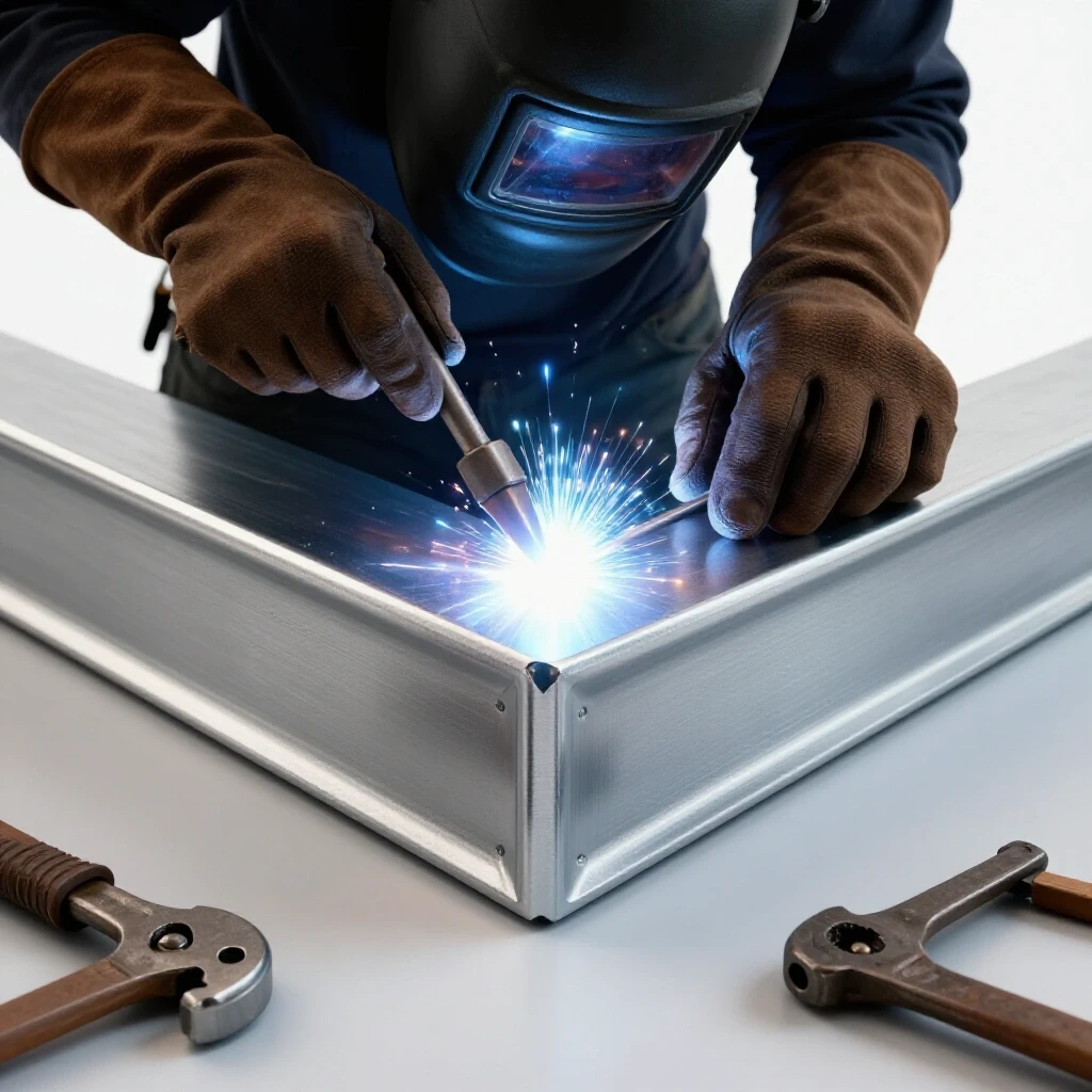
Body mechanics in fabrication involve the conscious alignment of your torso, arms, and hands to provide a stable platform for tool operation. Proper positioning reduces muscle fatigue and prevents the erratic movements that cause cutting errors. By treating your body like a tripod, you can maintain the steady hand required for fine-tuning metal edges or filling wide gaps.
When you are trying to trim a tiny sliver off a tube or weld across a gap, your stability is your greatest asset. I tell my students to use “triangulation.” This means keeping three points of contact with your work surface or the floor. If you are standing, lean your hip against the welding table. If you are sitting, rest your elbows on the surface. This physical bracing filters out the natural tremors in your hands.
I also track my breathing during critical tasks. Taking a deep breath and exhaling slowly as you move the torch or grinder helps maintain a consistent travel speed. This is especially important when you are working on a recovery task where the margin for error is slim. If your body is tense, your movements will be jerky, leading to inconsistent bead shapes or uneven cuts.
Assessing Dimensional Discrepancies in Steel Tubing
Dimensional assessment is the process of using precision measuring tools to quantify exactly how much a cut deviates from the intended design. This step is crucial because it dictates whether you need to remove more material or bridge a gap with filler metal. Without an objective measurement, you are merely guessing, which often leads to further mistakes.
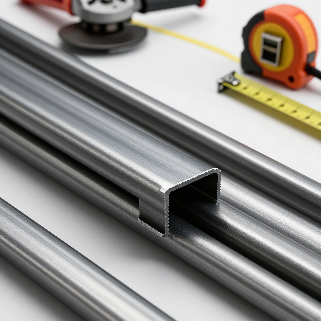
Before you reach for the welder, you must know the “why” and “how much” of the error. I use a combination of digital calipers, machinist squares, and a dedicated scribe. If a tube is cut at a 44-degree angle instead of 45, a simple visual check won’t suffice. You need to map the deviation. I recommend using a “fit-up log” to record these measurements, which helps you see patterns in your errors over time.
- Measuring the Gap: Use feeler gauges or the shank of a known-diameter drill bit to measure the space between two parts.
- Checking Squareness: Place a square against the long axis of the tube to see if the cut face is perpendicular or angled incorrectly.
- Scribe Lines: Always mark your intended “fix” with a sharp scribe line rather than a thick soapstone mark to maintain a 0.010-inch tolerance.
| Tool Type | Measurement Target | Precision Level |
|---|---|---|
| Digital Calipers | Wall thickness and outer diameter | +/- 0.001″ |
| Machinist Square | End-cut perpendicularity | High |
| Feeler Gauges | Gap width between joints | +/- 0.002″ |
| Contour Gauge | Complex notch accuracy | Medium |
Correcting Angle Errors Through Controlled Material Removal
Correcting an incorrect angle involves removing small amounts of metal from the high spots of a cut face to achieve the desired fitment. This requires a delicate touch and frequent checking against a reference square or the mating part. The goal is to create a flush interface that allows for even heat distribution during the subsequent welding process.
If you find that your miter cut is off by a degree or two, do not try to “eyeball” the fix with a large grinder. I prefer using a fine-grit flap disc (80 to 120 grit) or a hand file. A common rookie mistake is applying too much pressure, which generates excessive heat and removes too much material. Instead, use light, sweeping motions. Think of it like sanding wood; you want to “kiss” the metal rather than gouge it.
I once worked with a student who kept over-grinding his tubing. We started a drill where he had to remove exactly 1/16th of an inch from a scrap piece, measuring with calipers after every five strokes of the file. This built his muscle memory for how much force equates to material removal. Once you can feel the metal giving way, you gain the control necessary to fix a bad cut without making it shorter than necessary.
Bridging Wide Gaps with Advanced Puddle Control
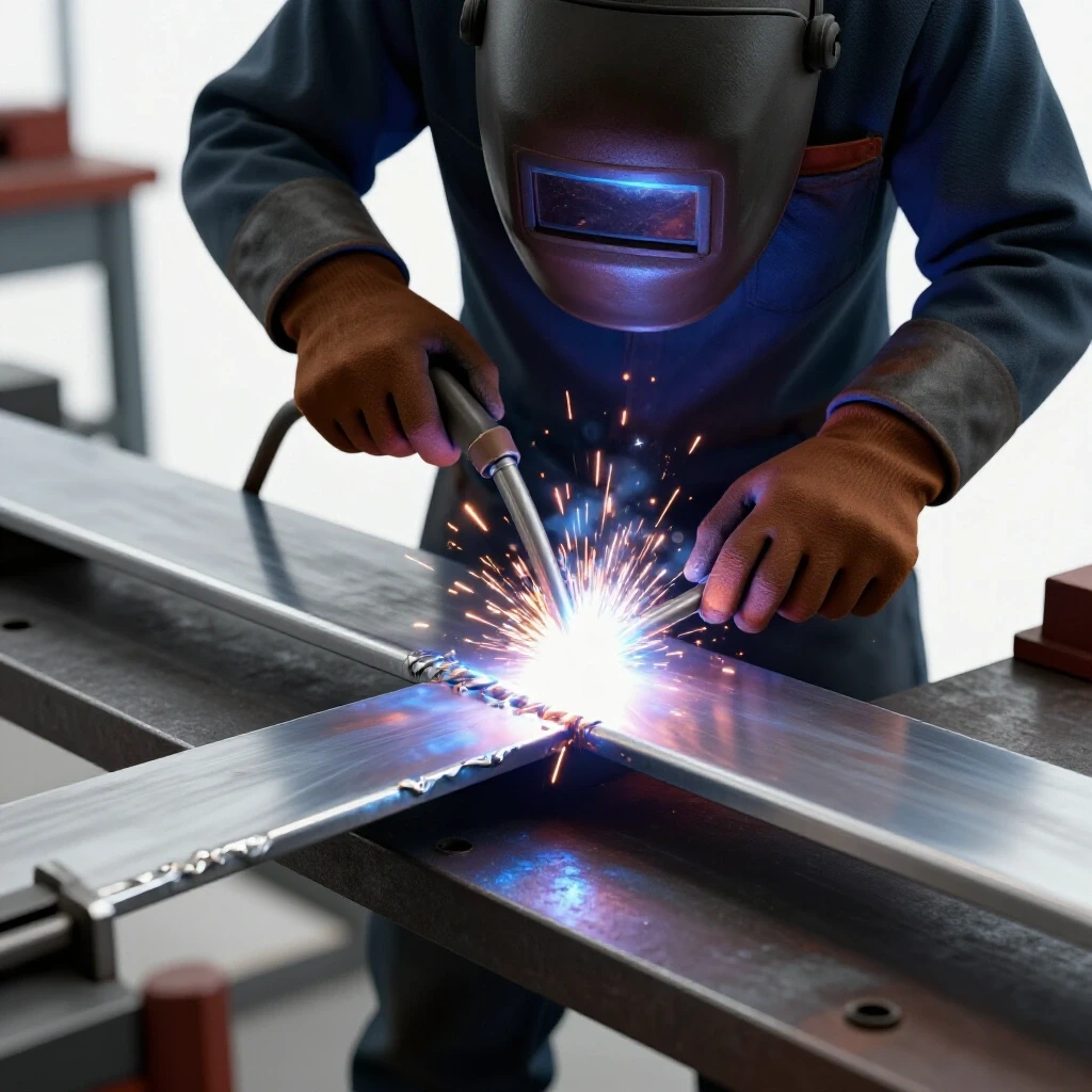
Bridging a gap refers to the technique of using a welding arc to deposit filler metal across a space that is wider than the standard fit-up tolerance. This requires precise management of the weld puddle’s surface tension and the heat input into the base metal. Mastering this skill allows you to save parts that were cut slightly too short.
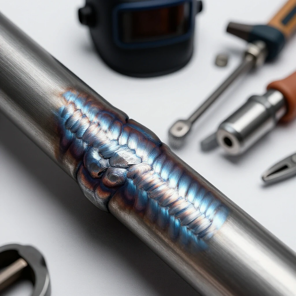
When a tube is short, you are often faced with a gap larger than 1/8 of an inch. In standard fabrication, we want tight fit-ups, but recovery often demands “buttering” the edges. This involves depositing a bead of weld on the end of the short tube to effectively extend its length before you attempt to join it to the other piece. You must monitor your heat input carefully to avoid blowing through the thin wall of the tubing.
- Travel Speed: Slow down your travel speed to 6–8 inches per minute (IPM) to allow the puddle to build up.
- Torch Angle: Use a 10–15 degree drag angle to push the metal into the gap.
- Arc Gap: Keep a tight arc gap of about 3/32″ to 1/8″ to maintain a focused heat zone.
- Oscillation: Use a slight side-to-side “weave” or “C” motion to tie the puddle into both sides of the gap.
Using Internal Sleeves to Restore Structural Integrity
Internal sleeving, also known as slugging, is a recovery method where a smaller diameter tube is inserted into the miscut sections to bridge a gap and provide internal reinforcement. This technique is used when the gap is too large to bridge with weld metal alone or when the joint requires additional strength. It provides a solid backing for a full-penetration weld.
If I have a tube that is a half-inch too short, I don’t just fill it with weld. I find a “slug”—a piece of tubing that fits snugly inside the main tubes. This slug should extend at least two diameters into each side of the joint. By welding the two main pieces to this internal sleeve, you create a very strong mechanical bond. This is a standard practice in many high-performance fabrication shops for repairing errors in tubular frames.
To do this correctly, you must ensure the internal sleeve is clean and free of rust. I recommend using “plug welds” or “rosebud welds” in addition to the butt weld at the seam. This involves drilling small holes in the outer tube and welding through them to the inner sleeve. This distributes the load and ensures the sleeve cannot move. It is a systematic way to turn a measurement failure into a reinforced success.
Physical Practice Drills for Consistent Weld Beads
Physical practice drills are repetitive exercises designed to build the hand-eye coordination and muscle memory required for consistent welding. By isolating specific movements, such as travel speed or torch angle, a fabricator can identify and correct technical flaws. These drills are the foundation of professional-grade fabrication skills.
I recommend a “bead-on-plate” drill for anyone struggling with inconsistent welds. Take a piece of scrap tubing and draw straight lines every half-inch. Practice running beads exactly on those lines. Your goal is to keep the bead width and height identical for the entire length of the tube. I track my progress by measuring the bead width with calipers. If my beads vary by more than 1/16 of an inch, I know I need to work on my travel speed consistency.
Another effective drill is the “gap-fill” exercise. Deliberately cut two pieces of scrap with a 1/8-inch gap and practice joining them. This teaches you how to read the “fluid puddle tension.” You will see the metal wanting to sag or pull away; your job is to use the torch to coax it across the bridge. Record your settings (Amperage, Voltage, Wire Speed) in a logbook so you can replicate your successes.
| Practice Step | Objective | Success Metric |
|---|---|---|
| Bead-on-Plate | Consistency in travel speed | Uniform bead width (+/- 1/16″) |
| Edge Buttering | Adding material to a short end | No cold-lap or undercut |
| Gap Filling | Bridging a 1/8″ void | Full fusion without blow-through |
| Corner Tacking | Maintaining alignment | Zero movement during cooling |
Setting Baseline Parameters for Gap Recovery
Baseline parameters are the specific machine settings, such as amperage, voltage, and gas flow, that provide a starting point for a welding task. Adjusting these parameters is necessary when moving from standard joinery to recovery work, as gaps require different heat profiles. Understanding these settings prevents common defects like porosity or excessive penetration.
When you are fixing a miscut part, you usually need to “run colder” than you would for a tight fit-up. If your amperage is too high, the heat will cause the edges of the gap to melt away, making the hole even larger. I typically drop my amperage by 10-15% when bridging a gap. This allows the puddle to freeze faster, which helps it span the distance between the two pieces of steel.
- MIG Settings: Lower the voltage slightly and increase the wire feed speed to create a “colder” weld that builds up more material.
- TIG Settings: Use a foot pedal to manually pulse the heat, allowing the puddle to solidify for a split second before adding more filler rod.
- Gas Flow: Maintain a steady 15–20 cubic feet per hour (CFH) of shielding gas to prevent atmospheric contamination in the wider weld zone.
Self-Assessing Weld Defects in Recovered Parts
Self-assessment is the systematic evaluation of your own work against established quality standards. By identifying defects such as undercut, overlap, or porosity, you can adjust your technique in real-time. This objective review is the fastest way to overcome a skill plateau and ensure your recovered parts are safe and functional.
After I finish a recovery weld, I always perform a visual inspection. I look for “undercut,” which is a groove melted into the base metal next to the weld toe. This usually happens if I hold the torch too long on one side or if the heat is too high. I also check for “overlap,” where the weld metal sits on top of the base metal without actually fusing to it. This is a sign that my travel speed was too fast or my heat was too low.
To measure your progress, I suggest taking high-resolution photos of your welds and viewing them on a large screen. It is amazing what you can see when a weld is magnified four times. You might notice small pinholes (porosity) that indicate your gas coverage was poor or the metal wasn’t clean enough. Use a “Weld Quality Checklist” to grade your work on a scale of 1 to 10. This data-driven approach removes the emotion from your practice and focuses on technical improvement.
Creating a Systematic Practice Log for Skill Tracking
A practice log is a written record of your shop sessions, including the techniques practiced, the parameters used, and the results achieved. Tracking these variables over time allows you to identify which adjustments lead to better results. It transforms random practice into a structured curriculum for self-improvement.
I have kept a logbook for over a decade. In it, I record the date, the material thickness, the joint type, and the specific challenge I was facing. For example, if I am practicing fixing short tubes, I will note the gap size and the amperage that finally worked. This prevents me from making the same mistake twice and gives me a “cheat sheet” for future projects.
- Define the Goal: (e.g., “Bridge a 3/16″ gap on 0.095 wall tubing”).
- Record Initial Settings: Amps, Volts, Tungsten size, or Wire diameter.
- Document the Result: Was there blow-through? Was the bead too tall?
- Adjust and Repeat: Change one variable at a time (e.g., “Lowered Amps by 5”) and note the difference.
- Review Weekly: Look back at your logs to see how your bead consistency has improved over the month.
Why Travel Speed Rules the Puddle
Travel speed is the rate at which the welding torch moves along the joint. It is the most critical variable in determining the heat input and the final shape of the weld bead. In recovery work, mastering travel speed allows you to control how much metal is deposited and how the heat is distributed.
If you move too slowly, the heat builds up, and the puddle becomes too large and difficult to manage. This often leads to the metal “falling through” the gap. If you move too fast, the metal doesn’t have time to fuse, resulting in a weak joint. I often use a metronome or a simple “one-one-thousand” count in my head to maintain a steady rhythm.
In my classes, I use a “travel speed metric” where students must weld a 6-inch bead in exactly 45 seconds. This forces them to synchronize their hand movement with the clock. When you are fixing a miscut part, this rhythm is what keeps the bead uniform. Consistency in your physical motion leads to consistency in the metallurgical bond.
The Importance of the Clean Zone in Metal Preparation
The “clean zone” is the area surrounding a joint that has been stripped of all contaminants, such as rust, oil, paint, and mill scale. Proper cleaning is essential for achieving a high-quality weld, especially in recovery situations where the arc must be stable to bridge gaps. A clean surface ensures that the filler metal bonds perfectly with the base material.
Many beginners underestimate the importance of preparation. They try to weld over the dark grey “mill scale” that comes on new steel. This scale has a higher melting point than the steel underneath, which causes arc instability. I always use a clean flap disc to grind back at least one inch from the edge of the cut. This “bright metal” zone allows the arc to flow smoothly and prevents impurities from being trapped in the weld.
When you are salvaging a part, you might be working with metal that has been sitting in the corner of the shop. It may have picked up moisture or shop grease. I use a dedicated degreaser (like acetone) after grinding to ensure the surface is chemically clean. This extra two minutes of prep can save you twenty minutes of grinding out a porous weld later.
Conclusion: Turning Errors into Expertise
Mastering the art of recovering miscut steel tubing is not about finding “hacks” or shortcuts. It is about applying the same rigorous technical standards to a repair as you would to a primary build. By focusing on your body mechanics, understanding your machine parameters, and maintaining a disciplined practice schedule, you turn every mistake into a lesson in metallurgy and physics.
The frustration of a bad cut is real, but it is also the best teacher you will ever have. Every time you successfully bridge a gap or sleeve a short tube, you are adding a high-level skill to your fabrication toolkit. Stay patient, keep your logbook updated, and remember that professional-grade results are the product of hundreds of hours of intentional, measured practice.
Frequently Asked Questions
What is the maximum gap I can safely bridge with just a welding bead?
Generally, for non-structural or cosmetic parts, you can bridge a gap up to 1.5 times the thickness of the metal. However, for structural tubing, any gap wider than 1/16 of an inch should be addressed by either buttering the edges or using an internal sleeve to ensure full fusion and strength.
How do I know if I should use an internal sleeve or just fill the gap?
If the gap is wider than 1/8 of an inch on structural tubing (like a roll cage or vehicle frame), an internal sleeve is highly recommended. It provides a mechanical backup and ensures the joint can handle the intended loads. If the part is purely decorative, a careful gap-fill with the welder is usually sufficient.
Why does my weld keep blowing through the edge of the tube?
Blow-through is usually caused by too much heat (amperage) or a travel speed that is too slow. When you reach the edge of a tube, there is less metal to soak up the heat. Try lowering your amperage or using a “pulsing” technique with your trigger or foot pedal to let the metal cool slightly between deposits.
Can I use a different type of steel for the internal sleeve?
It is best to match the material as closely as possible. If you are welding mild steel tubing, use a mild steel sleeve. Using a different alloy can lead to unpredictable weld behavior and potential cracking due to different rates of thermal expansion and contraction.
How do I fix a tube that was notched at the wrong angle?
If the notch is too deep on one side, you can “butter” that side with weld beads to add material back. Once the weld has cooled, use a hand file or a grinder to re-shape the notch to the correct angle. Always check the fit-up frequently during this process to avoid removing too much material.
What is the best way to keep tubes aligned while welding a gap?
Use “strongbacks” or external jigs. You can clamp a piece of angle iron across the joint to keep the two tubes perfectly straight while you bridge the gap. This prevents the heat of the weld from pulling the tubes out of alignment as the metal shrinks.
Does the wall thickness of the tubing change how I fix a mistake?
Yes. Thinner walls (like 0.065″) are much more sensitive to heat and blow-through. You must be much more precise with your amperage and travel speed. Thicker walls (like 0.120″ or 0.250″) allow for more heat and are generally easier to bridge gaps on because they act as a larger heat sink.
How can I tell if my “fix” is strong enough?
A good fix should have no visible defects like undercut or porosity. The weld bead should be slightly crowned and fused deeply into both sides of the joint. If you are unsure, you can perform a “dye penetrant test” to check for surface cracks that aren’t visible to the naked eye.
(This article was written by one of our staff writers, Thomas Langley. Visit our Meet the Team page to learn more about the author and their expertise.)