How to Translate CAD Drawings to Layout Marks on Steel (Fix)
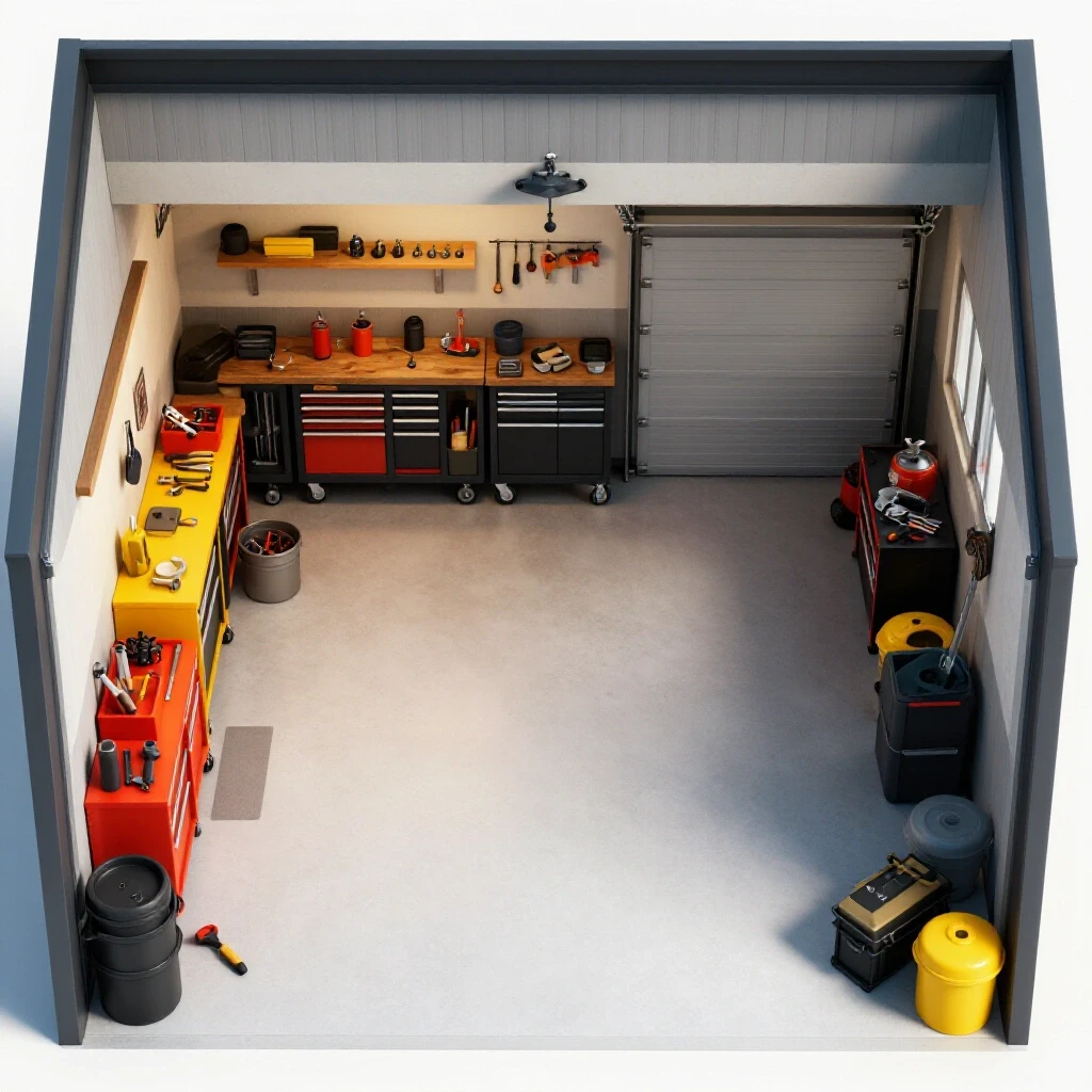
Scaling a fabrication shop from a personal garage into a high-output production environment is a transition filled with hidden friction. I remember the exact moment I realized my old methods were failing me; I was standing over a sheet of 3/8-inch plate, squinting at a smeared soapstone mark that was supposed to represent a complex pivot point from a digital model. My workshop was cluttered, my lighting was dim, and the “good enough” approach of my early years was costing me hours in wasted material and rework. That day, I stopped cutting and started thinking like a systems engineer.
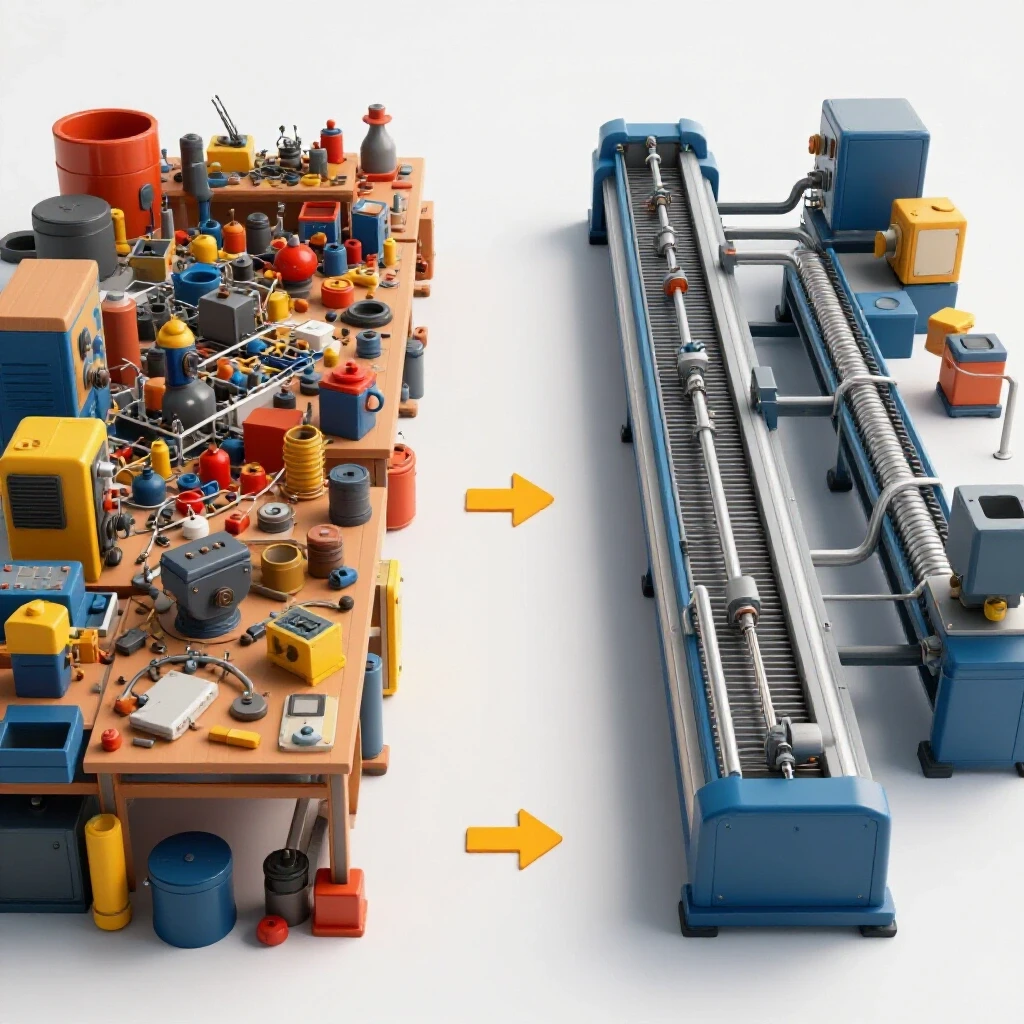
The challenge isn’t just about owning the right tools; it’s about the systematic movement of data from a computer screen to a physical surface with repeatable precision. When we move into advanced fabrication, the manual transfer of digital coordinates becomes a high-stakes bottleneck. If your layout is off by even a sixteenth of an inch, every subsequent process—drilling, machining, or fitting—compounds that error. To fix this, we have to look at the layout process as a dedicated manufacturing cell, supported by proper power, clean air, and a logical material flow.
Mapping the Precision Layout Zone Within a Lean Workflow
A dedicated layout zone is a specific area of the shop designed exclusively for the measurement, marking, and verification of workpieces before they hit the machines. In a lean setup, this zone must be positioned between material storage and the primary cutting stations to minimize the physical handling of heavy steel.
Efficiency in a micro-manufacturing environment is often measured by how few times you have to move a heavy plate. I’ve found that a linear flow pattern—where steel moves from the rack to a leveled layout table, then directly to the saws or CNC area—reduces “back-and-forth” travel by up to 40%. In my shop, I established a 3-foot minimum access zone around my layout table. This ensures that even when I’m handling a full 4×8 sheet, I have the physical clearance to move without tripping over cords or bumping into other machinery.
The floor load rating is another often-overlooked factor. A standard 4-inch residential concrete slab may crack under the concentrated weight of a heavy-duty layout table and a stack of steel plate. When I upgraded my space, I ensured my layout cell was positioned over reinforced sections of the slab, capable of handling at least 250 pounds per square foot. This stability is crucial; if your table isn’t perfectly level and rigid, your manual measurements will never truly reflect the precision of your CAD drawings.
Powering the Precision: 3-Phase Systems for the Layout Cell
A 3-phase power converter is an electrical device that takes standard single-phase residential power and creates a third “leg” of electricity, allowing you to run industrial-grade machinery. While layout is a manual task, the environment requires industrial-grade support systems that often demand this type of power.
When I integrated my first rotary phase converter, my primary goal was to run a high-capacity air compressor and industrial lighting. For accurate marking, you need high-intensity, flicker-free LED lighting that mimics natural daylight. This reduces eye strain and eliminates the shadows that lead to parallax errors when reading a scale. I recommend a lighting setup that delivers at least 100 foot-candles at the table surface.
Beyond lighting, 3-phase power allows for the use of high-efficiency dust extractors that keep the layout environment pristine. If you are scaling your shop, a 10-HP rotary phase converter is often the “sweet spot” for a growing facility. It provides enough overhead to run a layout cell’s support systems while leaving room for future CNC integration.
Table 1: 3-Phase Converter Options for Fabrication Shops
| Converter Type | Best Use Case | Efficiency | Typical Cost |
|---|---|---|---|
| Static Converter | Single machine, low start load | Low | $200 – $500 |
| Rotary Phase Converter | Multiple machines, high starting torque | Medium-High | $1,000 – $3,500 |
| Digital Phase Shifter | Precision electronics, CNC controls | Very High | $3,000 – $7,000 |
Managing Air Quality to Protect Surface Integrity
High-volume clean air filtration is a system of blowers and filters designed to remove airborne particulates, such as grinding dust and smoke, from the shop environment. In a layout context, clean air is vital because fine metallic dust can settle on your steel, making it difficult for layout fluids to adhere and for scribes to leave a clean, visible line.
I’ve learned the hard way that a standard “shop vac” isn’t enough when you’re scaling up. You need a multi-stage cyclone dust collection system. For a layout zone, you should aim for a minimum of 1,000 CFM (Cubic Feet per Minute) of airflow. This ensures that the air in the immediate vicinity is turned over frequently enough to keep the workspace clear.
When designing your ductwork, focus on minimizing static pressure loss. Static pressure is the resistance the air faces as it moves through the pipes. Using smooth-walled rigid ducting instead of flexible ribbed hose can significantly improve the performance of your filtration system. I aim for a duct velocity of about 3,500 to 4,000 feet per minute to ensure that heavy steel particles don’t settle inside the pipes and create clogs.
The Physics of Transferring Digital Dimensions to Steel
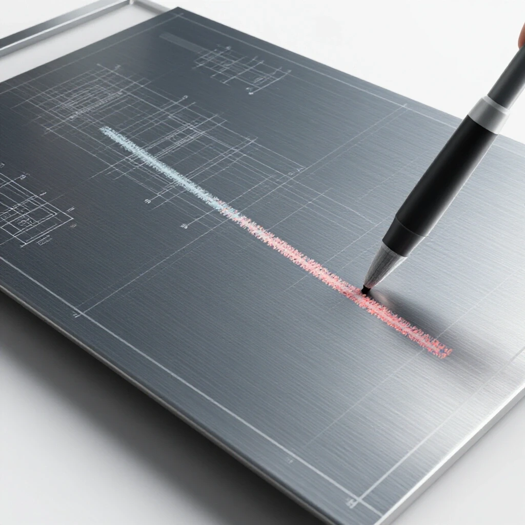
The core of this process involves moving vector-based dimensions from a digital file into physical marks on the workpiece. This requires a transition from the “perfect” world of CAD to the “real” world of physical tolerances. The “fix” for most layout errors is a combination of proper surface preparation and the use of precision hand tools.
I always start by applying a layout fluid, often a blue or red dye, to the area of the steel I’m working on. This creates a high-contrast surface where a scribe can leave a hair-thin, bright line. Without this, you are essentially guessing where your mark is against the dark, textured surface of the mill scale.
Precision Layout Tool Checklist:
- Carbide-Tipped Scribe: Used for drawing the actual lines. It must be sharp enough to catch the metal, not just the dye.
- Spring Dividers: Essential for transferring radii and stepping off equal distances from a CAD drawing.
- Center Punch and Hammer: Used to “set” the intersection points of your layout lines so a drill bit or tool won’t wander.
- Precision Square and Straightedge: These are your physical references for the X and Y axes defined in your software.
When I pull dimensions from a CAD file, I never measure from “feature to feature.” This leads to “tolerance stack-up,” where small errors in each measurement add up to a massive error at the end of the part. Instead, I establish a “datum edge”—a single, perfectly straight edge of the steel from which every single measurement is taken. This mirrors how a CNC machine operates, using a 0,0 coordinate as the anchor for all geometry.
Establishing Datums and Reference Lines
A datum is a fixed starting point or reference surface from which all other measurements are derived. In a digital drawing, this is your origin point. On a piece of steel, this is typically the cleanest, straightest factory edge or a line you have specifically machined to be true.
In my shop, I use the “3-4-5 rule” to ensure my manual layout lines are perfectly square to my datum edge. If I measure 3 inches along the datum and 4 inches out perpendicularly, the diagonal between those two points must be exactly 5 inches. If it isn’t, the geometry of the entire part will be skewed. This is a simple, analog way to verify that your manual work matches the mathematical perfection of your CAD model.
For complex curves or hole patterns, I use dividers to “step off” distances. If the CAD drawing shows a hole pattern with 2-inch centers, I set my dividers using a precision steel rule and then “walk” the dividers along my layout line. This technique is significantly more accurate than using a tape measure, as it eliminates the visual error of trying to align a tape’s markings with your scribe lines.
Software Integration and Physical Verification
While we are focusing on manual marking, the data comes from the software. To optimize this, I print “full-scale” 1:1 templates for complex parts when possible. However, paper expands and contracts with humidity, which can introduce errors. The professional “fix” is to use the digital coordinates as a guide and manually map them using a high-quality steel rule and dividers.
I maintain a “layout log” where I record the X and Y coordinates of every critical point from the CAD file. I then check these off as I punch them into the steel. This systematic approach prevents the “where was I?” syndrome that often happens in a busy shop. It’s about creating a closed-loop feedback system where the physical mark is verified against the digital coordinate before any cutting begins.
Layout Accuracy Benchmarks:
- General Fabrication: +/- 1/16 inch
- Precision Machine Bases: +/- 0.015 inch
- Critical Hole Patterns: +/- 0.005 inch (Requires use of a height gauge and surface plate)
Optimizing the Layout Environment for Visibility and Accuracy
The physical environment of your shop directly impacts the quality of your layout. Beyond 3-phase powered lighting and filtration, the layout table itself must be a tool of precision. I use a heavy, 1-inch thick steel plate table that has been ground flat. If your table is bowed, your straightedges will rock, and your measurements will be false.
I also incorporate a “clean zone” protocol. No grinding or welding happens within 5 feet of the layout table. This prevents sparks from pitting the surface of the table or landing on the workpiece. It also ensures that the layout fluid dries cleanly without trapping airborne debris. This might seem like overkill, but in a professionalized shop, these small details are what separate a hobbyist from a micro-manufacturer.
Environmental Maintenance Intervals:
- Table Surface Cleaning: Daily (remove all dust and oils)
- Lighting Inspection: Monthly (replace flickering or dimmed LEDs)
- Air Filter Check: Every 50 operating hours (clean or replace based on static pressure readings)
- Tool Calibration: Quarterly (check squares and rules against a known standard)
The Financial Reality of Scaling Layout Operations
Transitioning to these advanced methods involves capital costs. A high-quality layout table can cost between $2,000 and $5,000. A rotary phase converter and the associated wiring might run another $3,000. However, I look at these costs through the lens of “capital depreciation” and “scrap reduction.”
If a $5,000 investment in layout infrastructure reduces your scrap rate by 10% and saves you 5 hours of rework per week, the system pays for itself in less than a year. In my 20 years of operation, I’ve found that the most expensive tool is the one that produces an inaccurate part. By investing in the “front end” of the fabrication process—the layout—you ensure that the “back end” (the actual cutting and assembly) runs smoothly.
Conclusion and Next Steps
Moving from a basic setup to a highly efficient, semi-professional workshop requires a shift in mindset. You are no longer just “marking steel”; you are executing a precision data transfer. By organizing your shop layout to favor linear flow, ensuring your electrical and air systems support a clean and bright environment, and using the right precision hand tools, you can bridge the gap between digital design and physical reality.
The first step is to audit your current layout area. Is it well-lit? Is it flat? Do you have a dedicated set of precision tools that never leave that table? Start by establishing a datum-based marking system on your next project. Use layout fluid, a sharp scribe, and take your measurements from a single reference edge. You will likely find that the time spent in careful layout is recovered ten-fold when the parts finally go together without a struggle.
FAQ: Precision Layout and Shop Optimization
What is the most accurate way to transfer a CAD radius to steel? The most accurate method is using a set of spring dividers. Set the points of the dividers against a precision steel rule to the exact radius dimension found in your CAD software. Place one point on the center-punched center point of the radius and scribe the arc. This is far more precise than trying to free-hand a curve or using a compass.
How do I prevent my layout lines from being rubbed off during handling? Use a high-quality layout fluid (like Dykem) and let it dry completely before scribing. Once your lines are scribed, use a center punch to “stitch” the lines at critical intersections. Even if the dye is rubbed off, the physical indentations in the steel will remain as a permanent reference.
Can I use a standard tape measure for layout from CAD? For general fabrication with a 1/16-inch tolerance, a tape measure is acceptable. However, for precision work, a steel rule or a vernier caliper is preferred. Tape measure hooks can have “play” that introduces errors, and the thickness of the markings can lead to inconsistent readings.
Why does my 3-phase converter matter for a manual layout station? While the marking itself is manual, the 3-phase converter powers the industrial-grade support systems. This includes high-output, flicker-free lighting and large-scale air filtration systems that keep the layout surface clean and visible.
What is “parallax error” in layout? Parallax error occurs when you view a measurement scale from an angle rather than straight on. This causes the mark on the scale to appear shifted relative to the workpiece. Proper layout station height and high-intensity lighting help you position your eyes correctly to avoid this.
How do I establish a 0,0 origin on a rough piece of steel? First, select the straightest factory edge as your X-axis. Then, use a precision square to scribe a line perpendicular to that edge near one corner. The point where that line meets the factory edge is your 0,0 origin. All dimensions from your CAD file should be measured from these two lines.
How often should I clean my shop’s air filtration filters? In a high-output shop, you should check your filters every 50 to 100 hours of operation. If you notice a drop in suction or see dust settling on your layout table, it’s time to clean or replace the filters. Monitoring static pressure with a simple gauge can tell you exactly when the filters are clogged.
What is the best way to mark hole centers for drilling? After scribing the intersecting lines for the hole center based on your CAD coordinates, use a small “prick punch” to create a tiny dimple at the exact intersection. Verify the location, then use a heavier center punch to enlarge the dimple. This provides a secure starting point for the drill bit.
Does temperature affect layout accuracy? Yes. Steel expands and contracts with temperature. If you are doing high-precision work (tolerances under 0.005″), try to perform your layout in a temperature-controlled environment. Large temperature swings between the CAD design phase and the layout phase can lead to measurable dimensional differences.
Is it worth buying a dedicated layout table? If you are scaling to a professional level, yes. A dedicated, ground-flat layout table provides a reliable reference plane that a standard workbench cannot match. It is the foundation of all your manual measurements.
(This article was written by one of our staff writers, Edward Sinclair. Visit our Meet the Team page to learn more about the author and their expertise.)