How to Weld a Leveling Base Plate for Heavy Machinery (Fix)
I remember the first time I tried to build a heavy-duty mounting base for a vintage milling machine. I had measured the floor, cut my 1/2-inch plate steel to size, and spent three hours cleaning the mill scale until the metal shone like a mirror. I felt confident. But as soon as I finished my final weld pass, I watched in frustration as the corner of the plate lifted nearly 3/16 of an inch off the table. My flat foundation had become a rocking chair.
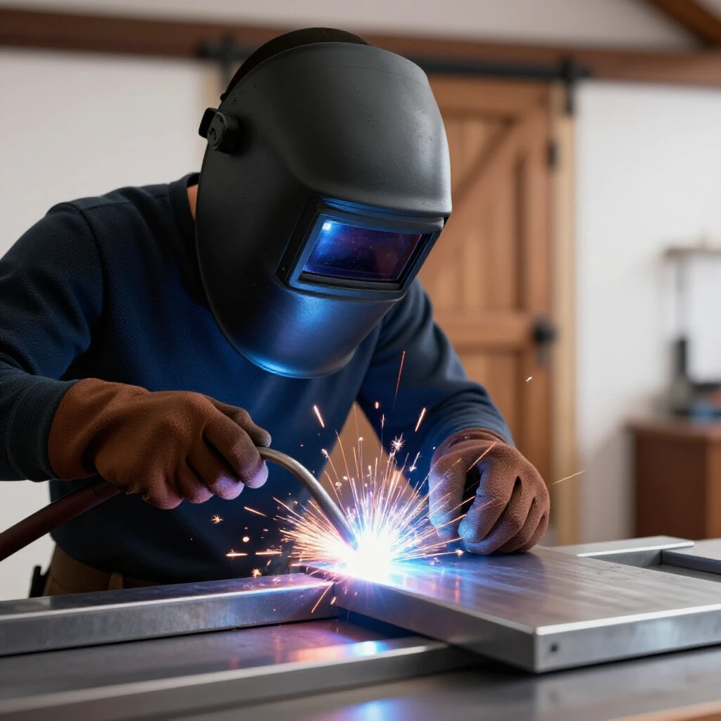
Thirteen years as a prototype technician taught me that steel is a living thing when heat is involved. It breathes, it pulls, and it fights back. If you are building a custom foundation for a lathe, a drill press, or a heavy fabrication table, you aren’t just sticking metal together. You are managing thermal energy. This guide focuses on the technical reality of fabricating adjustable mounting feet and structural plates that stay flat enough to keep your shop equipment stable and true.
Designing the Foundation: Blueprints and Material Preparation
Designing a structural mounting system requires a clear understanding of how raw stock translates into a finished assembly. This phase involves calculating the exact dimensions of your components while accounting for the material lost during the cutting process and the physical space required for weld beads.
Planning is where most projects fail before the welder even gets plugged in. When I start a build, I create a cut list that accounts for the “kerf.” The kerf is the width of the material removed by your saw blade or cutting torch. If you are using a standard abrasive chop saw, that kerf is usually 3/32 to 1/8 of an inch. If you ignore this, a four-piece frame can easily end up 1/2-inch short of its target dimension.
For heavy equipment foundations, I prefer using A36 mild steel plate. It is predictable and welds easily with standard MIG or TIG processes. I typically aim for a dimensional tolerance of +/- 1/16th inch. To achieve this, I use a layout dye or a fine-point scribe rather than a thick carpenter’s pencil. A pencil line can be 1/16 of an inch wide on its own, which is far too much room for error when you are trying to align bolt holes for leveling jacks.
| Cutter Type | Typical Kerf Width | Accuracy Range |
|---|---|---|
| Abrasive Chop Saw | 0.090″ – 0.125″ | +/- 0.060″ |
| Cold Saw | 0.075″ – 0.100″ | +/- 0.015″ |
| Portable Band Saw | 0.025″ – 0.040″ | +/- 0.030″ |
| Plasma Cutter (Manual) | 0.040″ – 0.060″ | +/- 0.080″ |
Calculating Bolt Hole Alignment and Clearance
Hole placement is critical when you need to thread in leveling bolts or anchor a machine to the floor. I never drill holes to the exact size of the bolt. Instead, I use “clearance holes.” For a 1/2-inch leveling bolt, I will drill a 9/16-inch or even a 5/8-inch hole. This extra space allows for minor adjustments if the weldment pulls slightly during cooling.
Understanding Material Behavior and Thermal Expansion
Metal expands when heated and contracts as it cools, a physical reality that dictates how a weldment will move. In fabrication, we must account for the yield strength of the steel and the specific ways that heat causes “angular distortion” in plate joints.
Steel has a thermal expansion coefficient that means it grows as you pump heat into it with a welding arc. When the weld bead cools, it shrinks. Because the weld is fused to the base metal, that shrinkage acts like a powerful winch, pulling the surrounding metal toward the center of the weld. This is called “angular pull.” If you weld only on one side of a plate, the plate will curl toward that weld.
In my experience, the thicker the plate, the more heat it can soak up before it deforms, but the forces of the shrinkage are also much stronger. I’ve seen 1-inch thick plates bow because a fabricator ran a single, massive bead without any counter-restraint. To manage this, you have to understand the elastic limit of your material. You want to stay within the range where the metal can “bounce back” rather than permanently deforming.
- Thermal Expansion: The increase in volume of the steel as temperature rises.
- Angular Distortion: The folding or “V” shape created when a fillet weld shrinks.
- Yield Strength: The point at which the steel will stay bent and won’t return to its original shape.
- Heat Dissipation Rate: How fast the metal pulls heat away from the weld zone, which is much slower in thinner gauges.
Building Workshop Jigs and Fixtures for Alignment
A fabrication jig is a temporary structure or setup used to hold components in the correct position during the welding process. Using fixtures ensures that parts stay square and flat by providing physical resistance against the forces of weld shrinkage.
I never weld a leveling base directly on a wooden workbench or a thin sheet-metal table. You need a flat, heavy surface to act as a heat sink and a mechanical restraint. If you don’t have a dedicated 1-inch thick welding platen, you can build a temporary fixture using heavy C-channel or I-beams. The goal is to clamp your workpiece so tightly that the metal cannot move while the weld is in its plastic (soft) state.
When setting up your fixture, consider the “span” of your clamps. If you only clamp the corners of a long plate, the center can still bow upward. I follow a rule of thumb: place a clamp or a heavy-duty hold-down every 8 to 10 inches along a joint. This distributes the pressure and prevents the plate from “oil-canning” or buckling in the middle.
- Clean the fixture surface of all weld spatter and debris.
- Position the primary base plate and check for flatness with a machinist’s straight edge.
- Use heavy-duty F-clamps or C-clamps to secure the plate to the table.
- Place copper or aluminum “chill blocks” under the weld zones if you need to pull heat away quickly.
- Verify the squareness of any vertical gussets using a precision square before tightening the final clamps.
The Strategic Tacking Process
Tack welds are small, temporary welds used to hold parts in alignment before the final welding passes are made. A proper tacking strategy involves placing small beads in a specific order to balance the initial stresses of the heat.
Tack welds are the “stitches” of the fabrication world. I see many beginners use tiny, weak tacks that pop as soon as the first real weld bead starts to pull. For a heavy base plate, your tacks should be about 1/4 inch to 1/2 inch long and have good penetration. I always place tacks in opposing pairs. If I tack the North side of a plate, the very next tack goes on the South side.
Spacing is also vital. For a standard 12-inch square base plate, I place tacks at every corner and in the center of each side. This creates an “anchor grid.” If you are welding a threaded nut to the plate for a leveling foot, tack it in four places (12, 6, 3, and 9 o’clock) before running the full circumference. This prevents the nut from tilting, which would make the leveling bolt bind later on.
- Tack Size: 2x the thickness of the thinnest material for small parts, or 1/2 inch for heavy plate.
- Tack Spacing: Every 3 to 5 inches for long seams.
- Inspection: After tacking, I always use a square and a level to verify the geometry. It is much easier to grind out a tack than to cut a full weld.
Mastering Weld Sequencing and Distortion Control
Weld sequencing is the planned order in which you lay down your weld beads to minimize the overall movement of the metal. By alternating sides and directions, you can use the shrinkage of one weld to counteract the shrinkage of another.
This is where the real “magic” happens in a workshop. If you start at one end of a plate and weld all the way to the other, the heat will build up in front of the arc, causing the gap to close or the plate to warp. I use a technique called “backstepping.” Instead of one long 10-inch bead, I lay down five 2-inch beads. I start the second bead 2 inches ahead of the first and weld back into the start of the first one.
Another essential method is “symmetrical welding.” If you are welding gussets onto a base plate, weld the left side of Gusset A, then the right side of Gusset B. By jumping around the project in a planned pattern, you keep the overall heat input even across the entire structure. This prevents one side of the base from getting significantly hotter than the other, which is the primary cause of twisting.
| Sequence Type | Best Application | Resulting Movement |
|---|---|---|
| Continuous Bead | Short joints (< 3″) | Minimal if clamped tight. |
| Backstepping | Long seams and plates | Significantly reduces longitudinal bowing. |
| Alternating Sides | T-joints and gussets | Balances angular pull to keep parts square. |
| Center-Out | Large flat surfaces | Pushes heat toward the edges to prevent center buckling. |
Correcting Heat Distortion and Final Straightening
Despite our best efforts, some movement is inevitable in heavy fabrication. Final straightening involves using controlled heat or mechanical force to bring a warped part back into the required dimensional tolerance.
If you finish your base and find a slight bow, don’t panic. I’ve had to “flame straighten” many projects. This involves using an oxy-acetylene torch to heat a small spot on the side opposite the warp. When that spot cools, it shrinks and pulls the plate back. It sounds counterintuitive—using heat to fix a heat problem—but it works because you are creating a localized “shrinkage point” to counter the original weld pull.
For minor adjustments, I often use a hydraulic press or even a heavy-duty vice. However, you must be careful not to exceed the yield strength of the steel to the point of cracking the welds. I always check my work with a precision straight edge and a feeler gauge. If a 1/2-inch plate is within 0.010 inches of flat across its width, it is usually more than sufficient for a machine base, as the leveling bolts will handle the rest of the floor’s irregularities.
- Identify the high spot using a straight edge.
- Mark the area requiring “shrinkage.”
- Apply heat in a “rosebud” or circular pattern until the steel hits a dull red (about 1,100°F).
- Allow the metal to air cool naturally; do not quench it with water, as this can make the steel brittle.
- Re-measure and repeat if necessary.
Practical Case Study: The Lathe Leveling Foot
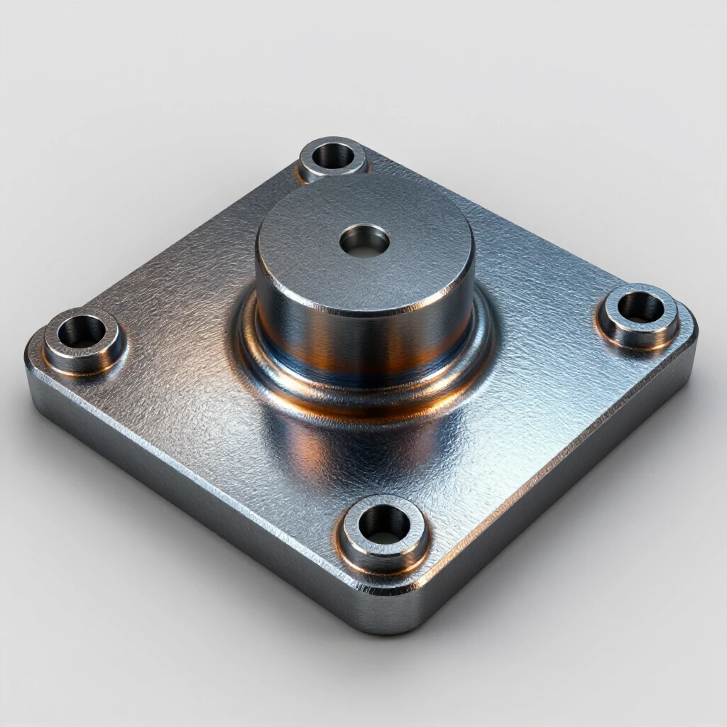
I recently built a set of four leveling feet for a 2,000-pound engine lathe. The base plates were 6-inch squares of 5/8-inch plate. I needed to weld a 1-inch thick threaded boss to the center of each plate. I knew that a heavy fillet weld around that boss would pull the corners of the plate upward, creating a “bowl” shape.
To prevent this, I clamped the base plate to my 1-inch thick steel table with four heavy C-clamps, one at each corner. I placed a 1/16-inch shim under the center of the plate, effectively “pre-stressing” it in the opposite direction of the expected warp. I tacked the boss in four places and then used a backstepping sequence to complete the weld.
After the metal had cooled completely—and I mean completely, back to room temperature—I released the clamps. The plate sprang back perfectly flat. That 1/16-inch shim was the difference between a professional result and a project that would have required hours of grinding or machining to fix.
Actionable Framework for Your Build
To keep your project on track, I recommend using a simple checklist for every base plate you fabricate. This ensures you don’t skip the small steps that lead to big errors.
- Verify Cut List: Did you account for the 1/8-inch kerf on all pieces?
- Clean Joints: Is all mill scale removed from the weld zone? (Essential for penetration).
- Check Fixture: Is the welding table clean and the clamps tight?
- Symmetrical Tacking: Are tacks placed in opposing pairs?
- Weld Sequence: Are you jumping between joints to distribute heat?
- Cooling Period: Did you let the part cool to the touch before removing clamps?
- Final Inspection: Use a square and straight edge to log the final dimensions.
Post-Weld Alignment Log
I keep a notebook in the shop to track how different materials react. For example, I might note: “6x6x1/2 plate, 3/4-inch boss, backstepped 4 segments, pulled 0.015″ at corners.” This data is invaluable for the next time I build something similar. It takes the guesswork out of the process and turns “feeling” into engineering.
Conclusion and Next Steps
Building a stable foundation for heavy machinery is a fundamental skill that separates hobbyist welding from professional-grade fabrication. By focusing on layout accuracy, understanding the physics of heat, and using disciplined welding sequences, you can create structures that are both durable and precise.
Your next step is to look at your upcoming project and identify the “shrinkage points.” Where will the heat be highest? Which way will the metal want to pull? Once you can visualize the movement before it happens, you can design a fixture or a sequence to stop it. Start small—perhaps with a simple workbench foot—and apply these principles. You will find that a little extra time spent in the layout and clamping phase saves a massive amount of time in the correction phase.
Frequently Asked Questions
How do I stop my base plate from bowing when I weld the mounting nuts?
The best way is to clamp the plate to a thick steel table and use a “pre-set” or shim. Place a thin piece of metal (about 1/32 to 1/16 inch) under the center of the plate before clamping the edges down. This bends the plate slightly in the opposite direction so that when the weld shrinks and pulls, it pulls the plate back to flat.
Should I use MIG or TIG for welding leveling bases?
MIG is faster and better for thick plates (1/4 inch and up) because it provides deep penetration with less overall heat soak time. TIG offers more control and is cleaner, but because it is slower, it puts more total heat into the part, which can lead to more warping if you aren’t careful with your sequence.
Why do my tack welds keep snapping?
This usually happens because the tacks are too small or the cooling metal is pulling with more force than the tack can handle. For heavy machinery bases, make sure your tacks are at least 1/2 inch long and that you have good fusion into the base metal. Also, avoid “cold starts” on your tacks.
How much clearance should I leave in the bolt holes?
For heavy equipment, a clearance of 1/16 inch to 1/8 inch over the bolt diameter is standard. This provides enough “slop” to account for minor weld distortion while still allowing the bolt head or washer to have plenty of surface area to grip the plate.
Can I weld the leveling feet while the machine is sitting on the base?
I strongly advise against this. The heat from welding can damage the machine’s bearings or internal components, and the machine itself acts as a massive heat sink that can lead to poor weld penetration. Always fabricate the base separately and let it cool before mounting the equipment.
What is the best way to clean mill scale?
Use a flap disc (40 or 60 grit) on an angle grinder. Mill scale is a hard oxide layer that acts as an insulator; if you don’t remove it, your arc will be unstable, and you may end up with “porosity” (tiny holes) in your weld.
How do I know if I’ve put too much heat into the part?
If the steel starts to turn a bright orange or if the weld puddle becomes very wide and difficult to control, you are putting in too much heat. Stop, let the part cool until you can touch it with a gloved hand, and then continue.
Do I really need a fixture table?
You don’t need a professional $3,000 table, but you do need a flat, rigid surface. You can use two pieces of heavy-walled square tubing clamped together to create a flat “ladder” frame to weld on. The key is that the fixture must be stiffer than the part you are welding.
What should I do if the plate is twisted, not just bowed?
Twisting is usually caused by an asymmetrical welding sequence. To fix it, you may need to use a combination of mechanical force (a big vice or press) and strategic heat shrinking on the corners that are “high.”
Is A36 steel the best choice for this?
Yes, A36 is the standard for structural DIY projects. It is affordable, has a predictable yield strength of 36,000 psi, and doesn’t require special pre-heating or post-heating like high-carbon or alloy steels.
(This article was written by one of our staff writers, Robert Kline. Visit our Meet the Team page to learn more about the author and their expertise.)