How to Nest Sheet Metal Cutting Layouts to Save Steel (Fix)
The transition from a hobbyist workshop to a high-output fabrication environment is rarely a single event. For me, it was a series of realizations that hit every time I tripped over a scrap pile or watched a 3-phase motor stall because my power converter wasn’t balanced. I spent twenty years evolving my shop from a corner of a garage to a systematic production floor. Along the way, I learned that efficiency isn’t just about how fast the machine moves, but how well you manage the space and materials around it.
When you begin scaling your operations, the “hidden” costs start to surface. You notice the minutes lost walking across the shop to find a tool and the dollars lost every time a jagged piece of expensive plate steel ends up in the bin. To fix these bottlenecks, we have to look at the shop as a single, integrated machine. This means optimizing everything from the electrical load on your main panel to the geometric arrangement of parts on a raw sheet.
Optimizing the Workshop Floor for Material Movement
A workshop layout is the physical map of your production efficiency, determining how raw stock moves from the delivery truck to the cutting table and finally to the shipping pallet. A well-designed floor plan minimizes the distance materials travel, reduces physical strain on the operator, and ensures that every square foot of space serves a specific purpose in the fabrication cycle.
In my early years, I made the mistake of placing my heavy material rack at the far end of the shop, away from the bay door. I spent hours every month wrestling 4×8 sheets of 10-gauge steel through a narrow aisle. Today, I advocate for a linear or U-shaped flow. Raw material should enter near your primary cutting station. This reduces the “material travel path,” a metric I use to track how many feet a piece of steel moves before it becomes a finished part.
I recommend a minimum 3-foot access zone around all major machinery. This isn’t just for safety; it is for maintenance. When your CNC gantry needs a rail cleaning or a motor replacement, you don’t want to spend four hours moving workbenches just to reach the bolts. If your floor is concrete, check the load rating. A full rack of steel and a heavy water table can exceed the PSI limits of a standard 4-inch residential slab, leading to cracks that throw your machinery out of level.
| Layout Feature | Hobby Setup (Typical) | Advanced Shop (Target) |
|---|---|---|
| Material Path | Erratic/Back-and-forth | Linear or U-shaped |
| Access Zones | Less than 1 foot | 3 feet minimum |
| Floor Load | Standard 4″ slab | Reinforced 6″ or thickened pads |
| Machine Zoning | Combined work areas | Dedicated Hot/Cold zones |
Powering the Transition: 3-Phase Systems and Electrical Loads
A 3-phase power system provides a more consistent and efficient delivery of electricity than standard single-phase power, which is essential for running industrial-grade fabrication equipment. By balancing the electrical load across three separate conductors, you can operate larger motors and high-output plasma power supplies without the voltage drops that plague smaller shops.
Most home-based or micro-manufacturing shops start with 240V single-phase power. However, as you integrate larger compressors and CNC systems, you will likely encounter equipment that requires 3-phase power. I solved this in my shop by installing a rotary phase converter (RPC). An RPC uses a single-phase motor to generate a third leg of power. The challenge is balancing the “wild leg.” If the voltage on that third leg is more than 5% higher or lower than the others, you risk overheating your sensitive electronics.
When planning your electrical layout, refer to the National Electrical Code (NEC) guidelines for motor loads. I always suggest over-sizing your sub-panel. If your current machines pull 60 amps, pull 100 amps to the shop. This prevents the lights from flickering every time the air compressor kicks on during a long cut. It also allows you to run your CNC electronics on a dedicated, “clean” circuit, separate from the heavy inductive loads of your motors.
- Rotary Phase Converter: Best for varying loads; uses a transformer and a motor to create the third phase.
- Static Phase Converter: Cheaper, but only starts the motor; the motor then runs at about 2/3 power.
- Variable Frequency Drive (VFD): Excellent for single-motor applications; allows for speed control and soft starts.
Managing Air Quality in High-Output Cutting Zones
High-volume air filtration is the process of capturing and removing fine metallic dust and hazardous fumes generated during thermal cutting and grinding operations. Effective systems rely on calculated CFM (Cubic Feet per Minute) requirements and strategic duct design to ensure that the air remains breathable and the shop surfaces stay clean.
I cannot stress the importance of air quality enough. In a high-output environment, a CNC plasma table can fill a 2,000-square-foot shop with smoke in minutes. I designed my filtration system around a 5-HP cyclone dust collector. To make this work, you have to understand static pressure loss. Every foot of ducting and every 90-degree bend creates resistance. If you use corrugated flex hose, you lose significantly more suction than if you use smooth-walled spiral pipe.
For a standard cutting table, you should aim for an air velocity of at least 3,500 to 4,000 feet per minute (FPM) inside the ducts to keep heavy metal dust from settling and clogging the pipes. OSHA standards for indoor air quality are a good benchmark here. I use a multi-stage filtration approach: a water table to catch the bulk of the dross and an overhead hood with a MERV 15-rated filter to scrub the fine particulates.
- Calculate Total CFM: Sum the requirements of all tools that will run simultaneously.
- Size the Main Trunk: Use a larger diameter pipe near the collector, tapering down as you reach individual tools.
- Minimize Bends: Use two 45-degree elbows instead of one 90-degree elbow to reduce turbulence.
- Install Blast Gates: Close off suction to machines not in use to maximize pull at the active station.
Strategic Part Arrangement for Maximum Material Yield
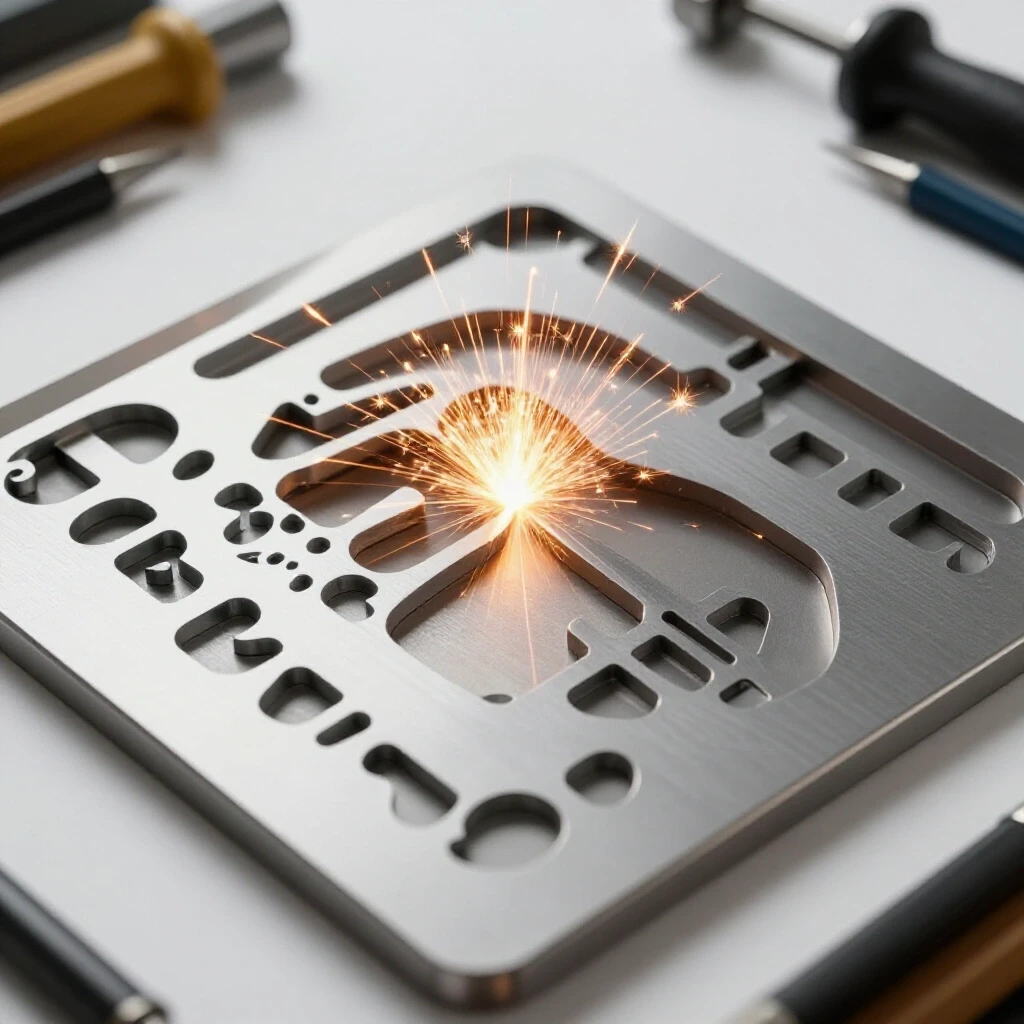
Maximizing sheet utilization is the practice of geometrically organizing 2D parts on a metal sheet to minimize the remaining scrap “skeleton.” By focusing on tight spacing, part nesting, and common-edge strategies, a fabricator can significantly reduce the amount of wasted material and improve the overall profitability of every project.
When I first started, I would just throw parts onto a sheet in the order I needed them. I quickly realized I was throwing away 30% of my material. Improving your yield starts with manual spatial reasoning. Think of it like a puzzle. If you have a large L-shaped bracket, you can often “interlock” a second bracket by rotating it 180 degrees. This creates a rectangular footprint that is much easier to fit into a corner of the sheet.
Another technique I use is “common-line” planning. If two parts have a straight edge of the same length, I place them so those edges are separated only by the width of the kerf (the material removed by the cutter). This allows one pass of the torch to cut two edges at once. Not only does this save steel, but it also reduces the total “torch-on” time, extending the life of your consumables. I often use simple paper templates or basic vector drawing tools to mock up these arrangements before I ever touch the machine.
- Kerf Allowance: Always account for the thickness of the cut (usually 0.040″ to 0.060″ for plasma).
- Edge Margins: Keep parts at least 0.25″ from the edge of the sheet to ensure the torch doesn’t lose its arc.
- Bridge Cutting: Connect small parts with tiny tabs of metal to keep them from falling into the water table or tipping up.
- Grain Direction: If the steel has a visible grain or rolling direction, ensure all structural parts are oriented the same way for strength.
Integrating CNC Systems into the Production Workflow
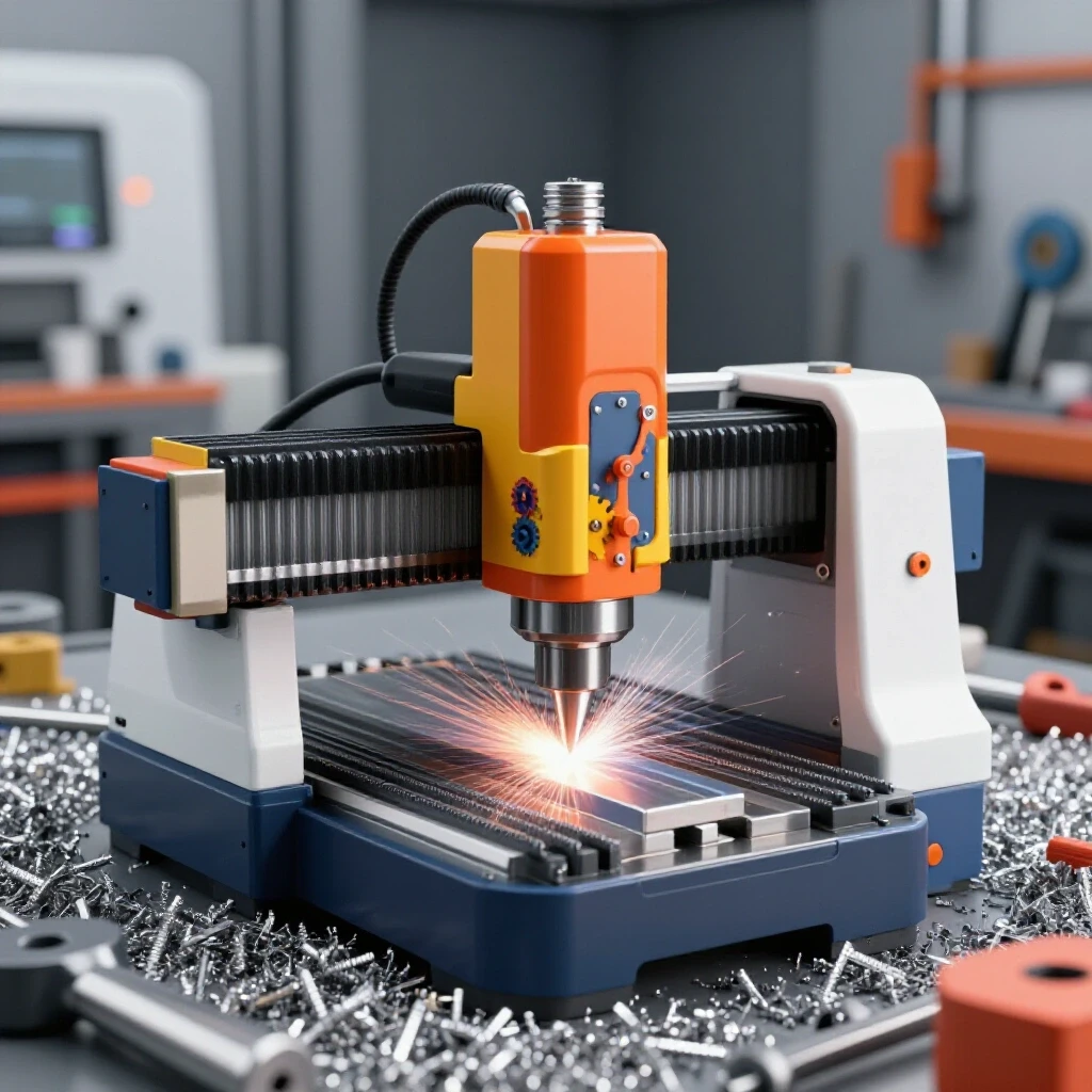
CNC integration is the systematic process of bringing automated machinery into a manual workshop to increase precision and throughput. This involves more than just plugging in the machine; it requires leveling the hardware, managing data cables to prevent interference, and establishing a repeatable workflow from drawing to finished cut.
The jump to CNC was the biggest hurdle in my shop’s evolution. It wasn’t the software that tripped me up; it was the physical setup. A CNC table must be perfectly level and square. If the rails are out of alignment by even a fraction of an inch, the gantry will bind, leading to “lost steps” and ruined parts. I use a machinist’s level and a large framing square to check my table every month.
Electrical noise is another silent killer of productivity. High-frequency starts from a plasma cutter can interfere with the low-voltage signals sent to your stepper or servo motors. I learned the hard way that you must keep your power cables and data cables in separate trays. Use shielded cables and ensure your machine is grounded to a dedicated copper rod driven into the earth, not just the building’s electrical ground. This prevents the “ghost in the machine” issues that cause the gantry to veer off course mid-cut.
| Component | Function | Maintenance Interval |
|---|---|---|
| Gantry Rails | Guides the cutting head | Weekly (Clean and lube) |
| Stepper Motors | Controls precise movement | Monthly (Check connections) |
| Torch Height Control | Maintains optimal arc gap | Daily (Check for debris) |
| Water Table | Catches dross and fumes | Quarterly (Clean out sludge) |
Measuring Success with Actionable Metrics
To know if your workshop optimizations are working, you must track the data. I keep a simple log next to my cutting station. I track “Sheet Yield Percentage,” which is the area of the finished parts divided by the total area of the raw sheet. In a professional micro-manufacturing environment, you should be aiming for a yield of 75% or higher. If you are consistently below 60%, your part arrangement strategy needs an overhaul.
I also track “Machine Uptime.” If your CNC table is sitting idle because you are busy moving material or waiting for the air compressor to catch up, that is a layout bottleneck. My goal is to have the machine running 4 hours for every 8-hour shift. The other 4 hours are spent on setup, loading, and unloading. By refining my material flow and air filtration, I was able to increase my uptime by 20% in just six months.
- Scrap Weight: Weigh your scrap bin weekly. A decreasing weight relative to your output means your nesting is improving.
- Electricity Usage: Monitor your bill after installing a phase converter to ensure you aren’t leaking power through an unbalanced “wild leg.”
- Consumable Life: Track how many pierces you get per nozzle. Better air filtration leads to longer consumable life.
Conclusion: Taking the First Steps Toward Professional Efficiency
Moving your shop from a hobby-level setup to a semi-professional production space is a marathon, not a sprint. The key is to address the fundamentals first. Start by looking at your floor. Can you move a sheet of steel from the door to the table without moving three other things? If not, that is your first project.
Once the flow is established, look at your power and air. These are the lifeblood of your machinery. A stable 3-phase supply and a clean breathing environment will do more for your long-term productivity than any new tool ever could. Finally, master the art of the manual layout. Every time you interlock two parts or share a cutting line, you are putting money back into your pocket.
Fabrication is as much about the process as it is about the product. By applying these lean principles and focusing on the technical details of your shop’s infrastructure, you can scale your operations with confidence. The transition might be challenging, but the result—a shop that works as hard as you do—is worth every hour of planning.
FAQ
What is the best way to start organizing parts on a sheet without expensive software? I recommend using basic vector-based drawing programs or even physical paper templates cut to scale. Start by placing your largest, most complex parts first, then fill the remaining gaps with smaller components. Rotating parts 90 or 180 degrees often reveals hidden space that you wouldn’t see at first glance.
How do I know if I need a rotary phase converter or a VFD? If you are powering an entire shop with multiple 3-phase machines, a rotary phase converter is usually the better choice because it provides power to a dedicated 3-phase sub-panel. If you only have one machine with a 3-phase motor, a VFD is often cheaper and allows you to control the motor’s speed.
Why does my plasma cutter keep “flaming out” during long cuts? This is often caused by a drop in air pressure or moisture in the lines. Ensure your compressor can maintain a CFM rating that exceeds your torch’s requirement by at least 20%. Additionally, check your filtration system; even a small amount of oil or water in the air can ruin a cut and destroy your consumables.
How much space should I leave between parts on a cutting layout? A good rule of thumb is to leave a gap equal to twice the width of your kerf. If your torch removes 0.060″ of material, leave at least 0.120″ between parts. This ensures that the heat from one cut doesn’t warp the edge of the adjacent part and prevents the torch from “jumping” to the wrong path.
What is the “wild leg” in a 3-phase system? In a rotary phase converter setup, the “wild leg” is the third line of power generated by the converter’s motor. It often has a higher voltage relative to ground than the two lines coming from your utility. It is critical to identify this leg and ensure it is never connected to the control circuits or sensitive electronics of your CNC system.
How do I calculate the static pressure loss in my dust collection ducts? Static pressure loss is calculated based on the duct diameter, length, and the number of bends. Smooth-walled pipes have a lower “friction coefficient” than flexible hoses. Most manufacturers provide charts that show pressure loss per 10 feet of pipe. You want to ensure your fan can overcome this total resistance while still moving the required CFM.
Can I run a CNC plasma table on a standard 4-inch concrete garage floor? Yes, but you must be careful with weight distribution. A large water table filled with several hundred gallons of water, plus the weight of the steel, can put significant stress on the slab. If you notice cracks forming, you may need to cut out a section of the floor and pour a thickened reinforced pad to support the machine’s weight.
What is “common-line cutting” and is it always a good idea? Common-line cutting is when two parts share a single cut line. It saves material and time, but it can be tricky. It requires very precise machine calibration and a consistent kerf. If your machine has any “backlash” or play in the gears, the parts may not come out perfectly square, so I suggest practicing with scrap before using it on expensive plate.
How do I ground my CNC table to prevent electrical interference? The most effective method is to drive a dedicated copper grounding rod at least 8 feet into the ground near the machine. Connect the table frame, the gantry, and the plasma power supply to this rod using heavy-gauge braided copper wire. This provides a “path of least resistance” for electrical noise, keeping it away from your motor controllers.
What is the most common mistake when scaling a fabrication shop? The most common mistake is focusing on the machine rather than the workflow. Many shop owners buy a bigger, faster machine but don’t change their floor layout or material handling. This just creates a bigger bottleneck at the cutting table. Always optimize your space and your process before you increase your raw cutting capacity.
(This article was written by one of our staff writers, Edward Sinclair. Visit our Meet the Team page to learn more about the author and their expertise.)