How to Prevent Costly CNC Machine Setup Errors (DIY Fix)
I have spent the last 14 years standing on concrete shop floors, often surrounded by the hum of machinery and the smell of cutting fluid. In that time, I have learned that the most expensive sound in a workshop is not the roar of a jet engine or the bang of a heavy press. It is the sharp, metallic “crack” of a CNC spindle hitting a hardened steel vise because a coordinate was off by a fraction of an inch. When you are working in a home shop or a small garage, these errors do more than just ruin a part; they drain your budget and shake your confidence in your structural designs.
My background in mechanical engineering has taught me that precision is not just about making parts look good. It is about safety. If a CNC machine cuts a joint slightly out of square, the resulting gap can lead to a major heat affected zone weakness when you try to weld it later. This guide focuses on the manual checks and physical principles you need to master to ensure your machine is ready to cut safely and accurately every time. We will look at how to verify your machine’s physical alignment and tool positions to prevent the kind of mechanical failures that lead to wasted material and potential injury.
Establishing a Reliable Workpiece Zero for Structural Accuracy
Workpiece zeroing is the process of telling your machine exactly where the material starts in 3D space. By using manual tools like edge finders, you ensure the cutter moves exactly where the design intends, preventing structural misalignment that could lead to part failure or wasted stock. This step is the foundation of every successful cut you will ever make.
When I first started inspecting industrial steel components, I saw how a 0.020-inch error at the machine could lead to a structural metal load capacity failure in a finished frame. If your “zero” is off, every hole, pocket, and profile is shifted. This creates uneven wall thicknesses that may not handle the intended stress. To prevent this, I always use a mechanical edge finder.
- Start by cleaning the workpiece and the vise jaws thoroughly. A single metal chip can throw your zero off by 0.005 inches.
- Run the spindle at a low RPM, usually around 1,000, and slowly approach the edge of the material.
- Watch for the moment the tip of the edge finder “kicks” or slides sideways. This is your physical zero point for that axis.
- Remember to account for the radius of the edge finder tip. If the tip is 0.200 inches wide, you must move the axis another 0.100 inches to find the true edge.
Using Manual Edge Finders for Lateral Precision
An edge finder is a simple mechanical tool that “kicks sideways” when it touches a part’s edge. It allows you to find the X and Y coordinates with high precision, which is critical for ensuring that bolt holes and load-bearing features are placed exactly where the engineering math requires. It is a low-cost tool that provides high-value data.
In my experience, relying solely on visual “eyeballing” is a recipe for disaster. I once watched a fabricator lose a $400 slab of 6061 aluminum because he thought he could see the center of a bore. He was off by 0.030 inches, which made the part’s wall too thin to support its rated load. Using an edge finder takes an extra two minutes, but it provides a physical guarantee that your part matches your blueprint.
Verifying the Z-Axis Zero to Prevent Spindle Crashes
The Z-axis zero tells the machine where the top of the material is located. Correcting this value manually prevents the tool from diving too deep into the material or the machine bed, which avoids the kind of impact that causes structural fatigue in the machine itself. This is often the most dangerous axis for setup errors.
I recommend the “paper flick” method or using a dedicated gauge block. Lower the tool slowly while moving a thin piece of paper back and forth on the material surface. The moment the paper snags, you have found your surface. This simple manual check is a key part of any workshop safety checklist. It ensures that your first plunge into the metal is controlled and predictable, rather than a violent collision.
Mastering Tool Length Offsets to Protect the Workpiece
Tool length offsets tell the machine how far each specific cutter extends from the spindle nose. Correcting these values manually prevents the tool from diving too deep into the material or the machine bed, which avoids the kind of impact that causes structural fatigue in the machine itself. Every tool in your rack has a unique length that must be recorded.
If you change a drill bit for an end mill but forget to update the offset, the machine still “thinks” it has the shorter tool installed. It will plunge the longer tool into the table to reach the programmed depth. I have seen this bend spindles and crack expensive carbide cutters. To avoid this, I treat every tool change as a high-risk event that requires a manual verification step.
- Measure every tool from the spindle face to the tip using a consistent method.
- Double-check the values entered into the machine’s offset table. A typo here is just as bad as a physical measurement error.
- Perform a “dry run” two inches above the part to see if the tool moves as expected before touching the actual metal.
Manual Touching and Gauge Block Methods for Depth Control
This involves lowering the tool until it just touches a known thickness, like a gauge block or a piece of paper, on the material surface. It is a fundamental safety check that ensures your Z-axis depth is accurate, preventing “plunge errors” that can ruin expensive workpieces. This method relies on physical contact rather than software assumptions.
When I am working on a project with tight tolerances, I use a 1-2-3 block. These blocks are precision-ground to exactly one, two, and three inches. By placing the block on the workpiece and bringing the tool down to touch it, I can set my offset with extreme confidence. This reduces the risk of welding defect troubleshooting later on, as your part depths will be exactly where they need to be for proper fit-up.
| Method | Estimated Accuracy | Best Use Case |
|---|---|---|
| Paper Snag | +/- 0.003″ | General fabrication and roughing |
| 1-2-3 Block | +/- 0.001″ | Precise pocket depths and structural tabs |
| Dial Indicator | +/- 0.0005″ | High-precision bearing bores |
| Electronic Probe | +/- 0.0002″ | Complex 3D surfacing |
Ensuring Machine Tram and Squareness for Structural Integrity
Tramming is the act of aligning the machine’s head and axes so they are perfectly perpendicular to the table. If a machine is out of tram, it cuts “steps” or angled faces, which creates poor fit-up for joints and can lead to a significant heat affected zone weakness during later welding. A “square” machine is the only way to get a “square” part.
I have inspected many failed frames where the builder blamed their welding technique. In reality, the CNC machine was out of tram. This caused the cut edges to be slightly angled, leaving a hidden gap at the root of the weld. When they applied heat, the gap caused the weld to pull unevenly, leading to structural cracking. Checking your tram with a dial indicator is a mandatory step for any serious builder.
- Mount a dial indicator in the spindle using a “sweeping” arm.
- Rotate the spindle by hand to check for variations in height across a 6-inch circle on the table.
- Adjust the machine head until the needle stays still (or within 0.001 inches) throughout the entire rotation.
Why Mechanical Squareness Matters for Load Paths
Mechanical squareness ensures that the forces acting on your finished part are distributed exactly as you calculated. If a mounting bracket is cut at a slight angle due to a machine alignment error, the bolt will exert uneven pressure, leading to localized stress concentrations. This can cause the material to fail well below its rated structural metal load capacity.
In engineering, we talk about “load paths.” This is the route that force takes through a structure. If your CNC setup is inaccurate, you are essentially diverting that path. Interestingly, even a small 1-degree tilt in a cut can increase the stress on a fastener by over 15%. By ensuring your machine is square, you are protecting the integrity of your entire project.
Fixture Clamping and Vibration Control in Garage Fabrication
Fixture clamping involves securing your workpiece so it cannot move or vibrate during the cutting process. Proper clamping pressure prevents material deformation and ensures garage fabrication safety by keeping the part from becoming a projectile. It is a balance between holding the part firmly and not crushing it.
I once saw a thin-walled tube get crushed in a vise because the operator was worried about it slipping. This created a permanent deformation that ruined the part’s structural physics. On the other hand, a loose part will vibrate, causing a poor surface finish and potentially breaking the tool. Using a torque wrench on your vise or clamps is a professional way to ensure consistent results.
- Always place clamps directly over the supports or the machine table to prevent bending the part.
- Use “soft jaws” for finished surfaces to prevent marring and stress risers.
- Listen to the sound of the cut; a high-pitched “scream” often indicates that the part is vibrating and needs better support.
Preventing Material Deformation from Over-Clamping
Over-clamping occurs when the force of the vise or clamps exceeds the yield strength of the material, causing it to bend or “bow.” When the clamps are released, the part springs back, and your once-flat surface is now curved. This is a common cause of poor joint preparation in structural projects.
To prevent this, I calculate the required clamping force based on the material’s thickness and the cutting forces involved. For aluminum, I am much gentler than I am with stainless steel. If you are worried about a part moving, use more clamps with less individual pressure rather than one clamp with excessive pressure. This distributes the load and keeps the material flat.
Diagnostic Inspection and the First-Part Checklist
A diagnostic inspection is a final series of checks performed before the “start” button is pressed. It involves verifying all offsets, clearances, and clamp positions to ensure the machine will operate safely. This checklist is your last line of defense against a costly setup error and a vital part of your workshop safety protocol.
I never start a program without walking through a mental (or physical) checklist. It is easy to get excited and skip a step, but that is exactly when accidents happen. In my 14 years of fabrication, I have found that the most experienced people are the ones who rely on checklists the most. They know that human memory is fallible, especially when a deadline is looming.
- Check Tool Clearances: Rotate the spindle manually to ensure the tool won’t hit the clamps.
- Verify Work Zero: Re-touch the edge finder to the corner to confirm the coordinates.
- Confirm Tool Offsets: Look at the tool in the spindle and the number on the screen.
- Review the Program: Ensure the speeds and feeds are appropriate for the material.
- Safety Gear: Confirm you are wearing your safety glasses and the machine guards are in place.
Why “Dry Runs” are Essential for Safety
A dry run is a simulation where the machine runs the program in the air, well above the actual material. This allows you to watch the tool paths and ensure there are no unexpected movements or “rapid” moves into the vise. It is the best way to catch a mistake before it becomes a disaster.
I always run my first part with the “Single Block” and “Feed Overrule” buttons active. This lets me step through the code one line at a time. If I see the tool moving toward a clamp, I can stop the machine instantly. This level of caution might seem slow, but it is much faster than rebuilding a machine or waiting six weeks for a new spindle.
Structural Joint Failure Analysis and CNC Accuracy
Structural joint failure analysis involves looking at why a joint broke and tracing it back to the original fabrication steps. Often, what looks like a welding error is actually a CNC setup error that created a “root gap” too large for the weld to bridge effectively. Precision at the machine leads to strength in the structure.
When a weld fails, I look at the “fit-up.” If the CNC cut the pieces with a 0.040-inch gap instead of a 0.010-inch gap, the welder has to use more heat to fill the space. This extra heat expands the heat affected zone weakness, making the metal around the weld brittle. By keeping your CNC setup tight, you allow for a smaller, cleaner weld that maintains the material’s original properties.
| Error Type | Effect on Joint | Resulting Failure |
|---|---|---|
| Out of Tram | Angled edges | Poor weld penetration |
| Zero Offset Error | Misaligned holes | Bolt shear or frame twist |
| Over-Clamping | Warped base plate | Uneven load distribution |
| Tool Vibration | Rough surface finish | Stress risers and fatigue cracks |
Maintaining Your Machine for Long-Term Reliability
Machine maintenance involves regular cleaning, lubrication, and inspection of the mechanical components. A machine that is covered in old chips and dried coolant will eventually lose its precision, leading to the very setup errors we are trying to avoid. Think of your machine as a precision instrument that needs constant care.
I have seen machines that were “lazy.” They wouldn’t move exactly 1.000 inch when told to because the lead screws were worn or dirty. This “backlash” makes it impossible to hit your numbers. By cleaning your machine after every use and checking the gibs and pre-loads, you ensure that the machine does exactly what the software tells it to do.
- Wipe down the ways and apply fresh oil daily.
- Check for “play” or movement in the table by using a dial indicator while pushing on the table by hand.
- Clean the spindle taper to ensure that tool holders sit perfectly flush every time.
The Role of Workshop Organization in Error Prevention
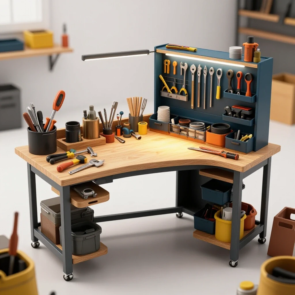
A clean and organized shop is a safe and accurate shop. If your tools are scattered and your measuring instruments are covered in grease, you are more likely to make a mistake during setup. Organization reduces the mental load on the fabricator, allowing you to focus on the physics of the cut.
I keep my edge finders, gauge blocks, and dial indicators in a dedicated “setup drawer.” They are cleaned and checked for accuracy once a month. This habit ensures that when I reach for a tool, I know I can trust the data it gives me. In garage fabrication safety, the environment is just as important as the equipment.
Conclusion: Building a Foundation of Precision
Preventing errors in your CNC setup is not about having the most expensive sensors or the newest software. It is about a disciplined approach to the physical reality of the machine. By mastering manual zeroing, tool offsets, and machine tramming, you are taking control of the structural integrity of your projects.
The lessons I have learned from 14 years of inspecting failures have taught me that the small details are what matter most. A well-set machine produces parts that fit together perfectly, which leads to stronger welds, safer structures, and a more rewarding hobby. Take the time to do the manual checks. Your spindle, your wallet, and your safety depend on it.
Frequently Asked Questions
What is the most common cause of a CNC spindle crash?
The most common cause is an incorrect tool length offset. This happens when the machine thinks a tool is shorter than it actually is, causing it to plunge into the workpiece or the table. Always verify your offsets with a dry run or a gauge block before cutting.
How often should I check the tram on my machine?
You should check the tram at least once a month, or any time the machine has experienced a “bump” or a minor crash. If you are starting a project with high structural requirements, a quick tram check is a good safety precaution to ensure your joints will be square.
Can I use a piece of paper to set my Z-zero accurately?
Yes, the “paper flick” method is a tried-and-true manual check. Standard printer paper is usually about 0.003 to 0.004 inches thick. By lowering the tool until it just snags the paper, you can set a zero that is accurate enough for most fabrication tasks.
What happens if my machine has “backlash”?
Backlash is the “slop” in the mechanical gears or lead screws. It causes the machine to move slightly less than commanded when it changes direction. This leads to parts that are undersized or holes that are oval instead of round, which can ruin the fit of structural components.
Why does clamping pressure matter for CNC accuracy?
If you clamp a part too tightly, you can deform the metal. Once the clamps are released, the part will “spring back” to its original shape, which means the features you just cut will no longer be in the right place. This is especially critical for thin-walled or long, slender parts.
How do I know if my edge finder is accurate?
You can test an edge finder by finding the edge of a known precision block, then rotating the block 180 degrees and finding the edge again. If the coordinates don’t match (after accounting for the block’s width), your edge finder may be bent or worn.
What is a “stress riser” in CNC machining?
A stress riser is a sharp corner or a rough surface finish left by a vibrating tool or a poor setup. These points concentrate the load on a part and are often the starting point for structural cracks. Ensuring a smooth finish and using radiused corners can prevent these failures.
Do I need to use a torque wrench for my vise?
While not strictly necessary for every job, using a torque wrench ensures consistent clamping pressure. This is very helpful when you are making multiple copies of the same part and want to ensure they all have the same level of accuracy and minimal deformation.
How does CNC accuracy affect my welding?
Better CNC accuracy leads to tighter “fit-up” between parts. Large gaps in a joint require more weld metal and more heat, which increases the risk of warping and creates a larger heat affected zone weakness. Precision machining makes for much stronger and cleaner welds.
What is the safest way to test a new CNC program?
The safest way is to run a “dry run” with the tool positioned several inches above the material. This allows you to observe the machine’s movements without any risk of a collision. Combined with a “Single Block” mode, this is the best way to catch errors before they cause damage.
(This article was written by one of our staff writers, James Harlan. Visit our Meet the Team page to learn more about the author and their expertise.)