Simple Quality Checks to Standardise Your Welding Shop (Fix)
I remember the exact moment I realized my workshop was no longer a hobby space but a liability. I was stepping over a tangled nest of extension cords to reach a manual band saw, only to realize I had left my square on the other side of the building. That three-minute round trip, repeated fifty times a day, was costing me hours of billable time every week. Over the last 20 years, I have transitioned from a cramped garage setup to a high-output fabrication facility by focusing on one thing: the systematic elimination of variables.
Scaling a fabrication shop is not just about buying a faster welder or a larger CNC plasma table. It is about creating an environment where the layout, the power, and the air quality work together to support consistent, repeatable results. When you move into professional-level production, the margin for error shrinks. You are no longer just making one-off parts; you are building a reputation for reliability. This requires a shift in mindset from “getting it done” to “building a process that does it right every time.”
Mapping Your Material Flow for Maximum Throughput
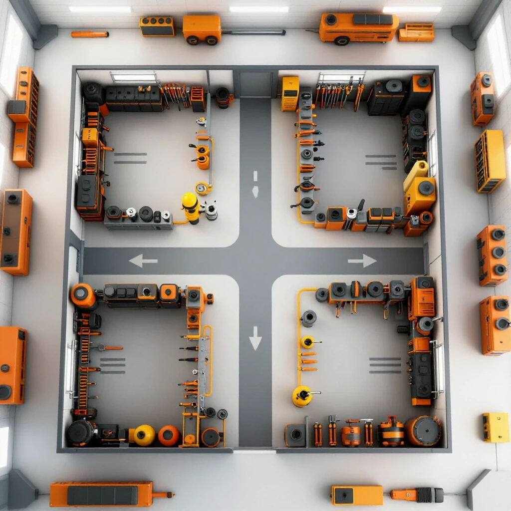
A material flow map is a visual representation of the path raw steel takes from the moment it arrives at your door until it leaves as a finished product. By analyzing these paths, you can identify physical bottlenecks that slow down your production.
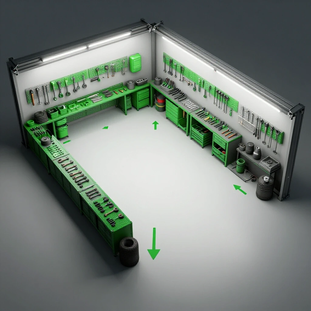
When I first audited my shop, my material path looked like a bowl of spaghetti. I was moving 20-foot sticks of tubing across the main walkway three different times just to get them to the cold saw. In a professional shop, every foot of movement costs money. You want a linear or U-shaped flow where materials move logically from storage to cutting, then to fit-up, welding, and finally to finishing.
Workshop Layout Flow Comparison
| Feature | Linear Flow | U-Shape Flow | Island/Cell Layout |
|---|---|---|---|
| Best For | High-volume, single products | Small to medium shops | Custom, low-volume work |
| Space Usage | Requires long, narrow bays | Efficient use of square rooms | High footprint per station |
| Material Entry | One end of the building | Same side as the exit | Multiple entry points |
| Throughput | Maximum efficiency | High flexibility | Lower, focused on detail |
Why Back-and-Forth Foot Traffic Kills Shop Throughput
This refers to the wasted time and energy spent by a fabricator moving between tools because the shop layout does not follow the sequence of operations. Reducing this traffic is the fastest way to increase your daily output without buying new machinery.
I once tracked my steps during a standard bumper build and found I walked nearly two miles inside a 1,200-square-foot shop. By reorganizing my workflow optimization tips into a “work cell” model, I cut that distance by 60%. I placed my most-used hand tools within a 3-foot reach of the welding table and positioned the grinding station between the fit-up area and the welding bench. This layout ensures that once a part enters the “welding zone,” it stays there until it is ready for the shipping pallet.
Establishing Machine Spacing and Access Zones
Access zones are the designated clear spaces around a machine required for safe operation, maintenance, and material handling. Maintaining these zones prevents accidents and ensures that one person’s work doesn’t stop another’s progress.
In my experience, the most common mistake is crowding a CNC plasma table setup. You need at least a 3-foot minimum access zone on all sides for loading sheets and clearing slag. If you are using a forklift or a gantry crane, that zone might need to be 6 to 8 feet. I use high-visibility floor tape to mark these boundaries. It sounds simple, but once those lines are down, the “creep” of scrap piles and tool carts magically stops, keeping the floor clear for actual production.
Powering the Evolution: Integrating 3-Phase Systems
A 3-phase power system provides three alternating currents that are out of phase with each other, allowing for more consistent and efficient power delivery to heavy industrial motors. Most residential shops start with single-phase power, which limits the size and duty cycle of the equipment you can run.
When you transition to industrial-grade CNC machines or high-output pulse MIG welders, you will likely encounter the 3-phase hurdle. Many of the best deals on used industrial equipment are 3-phase machines because the average hobbyist can’t power them. I solved this in my shop by installing a rotary phase converter, which allowed me to run a 10hp air compressor and a heavy-duty mill without upgrading my entire utility service.
3-Phase Power Converter Options
| Converter Type | Best Use Case | Pros | Cons |
|---|---|---|---|
| Static Converter | Starting motors only | Inexpensive, small | Reduced motor power (approx. 66%) |
| Rotary Converter | Multiple machines, CNC | Full power, very reliable | Noisy, higher idle power draw |
| Digital/Solid State | Sensitive electronics, CNC | Clean power, quiet | Most expensive option |
| VFD (Variable Frequency Drive) | Single motor speed control | Precise control, efficient | One VFD required per motor |
Balancing Electrical Phase Loads for Stability
Phase balancing is the process of ensuring that the electrical load is distributed as evenly as possible across all three legs of a 3-phase system. Unbalanced phases can lead to overheating motors and inconsistent performance in sensitive CNC electronics.
If you are using a 3-phase power converter, you must monitor the voltage between the legs. I keep a phase balancing log near my main panel. If I see a voltage drop of more than 5% on one leg when the CNC plasma is firing, I know I need to adjust which circuits are active. For anyone scaling a fabrication shop, understanding your power overhead is critical. Running too close to your limit will cause breakers to trip during a critical cut, potentially ruining a $500 sheet of specialized alloy.
Designing High-Volume Air Filtration and Dust Collection
Dust collection duct design involves the engineering of pipes and blowers to capture metal dust and fumes at the source before they circulate through the shop. Effective air management protects your health and prevents fine metallic dust from shorting out your expensive electronics.
Metal dust is different from sawdust; it is heavy, abrasive, and conductive. I learned the hard way that a standard shop vac is useless for a grinding station. You need a system that can maintain a high “static pressure” to pull those heavy particles through the ductwork. I designed my current system using 6-inch rigid ducting to minimize friction loss, ensuring I have at least 1,000 to 2,000 CFM (Cubic Feet per Minute) at the main intake.
Calculating CFM and Static Pressure for Metalworking
CFM (Cubic Feet per Minute) measures the volume of air moved, while static pressure measures the resistance that air faces within the ducts. In a welding shop, you need high CFM to pull fumes away from the welder’s face and high static pressure to lift heavy grinding dust.
- Welding Fume Extraction: Requires 600-900 CFM at the hood.
- Grinding Stations: Require 1,000+ CFM to capture heavy sparks and grit.
- Duct Velocity: Aim for 3,500 to 4,000 feet per minute (FPM) inside the pipes to keep metal dust from settling and clogging the system.
I recommend using a multi-stage cyclone dust collection system. The cyclone drops the heavy sparks and large chips into a metal bin before the fine dust reaches the expensive HEPA filters. This significantly extends the life of your filters and reduces the risk of a fire inside the ductwork.
Successfully Integrating CNC Tool Workflows
CNC integration is the process of moving from manual cutting and layout to automated, computer-controlled production. This transition is often the most difficult “fix” for a manual fabricator because it requires learning CAD (Computer-Aided Design) and CAM (Computer-Aided Manufacturing) software.
My first CNC plasma table setup was a revelation, but it also caused my biggest production bottleneck. I could cut parts faster than I could draw them. I had to standardize my tooling files and create a library of common brackets and tabs. This allowed me to go from a customer’s sketch to a finished cut in under fifteen minutes. If you are scaling up, do not underestimate the time needed to master the software side of the business.
Stepper vs. Servo Motors in Automation
Stepper motors move in fixed increments or “steps,” while servo motors use a closed-loop feedback system to constantly monitor and correct their position. Servos are generally faster and more accurate but come at a higher cost.
For most advanced home-based shops, high-torque stepper motors are sufficient. However, if you are running high-speed production where a single missed step could ruin a large part, closed-loop servos are worth the investment. I personally use servos on my gantry because the closed-loop feedback provides peace of mind; if the torch hits a tipped-up part, the machine stops instantly rather than trying to plow through and damaging the gantry.
Standardizing Output with Manual Verification Routines
Standardizing output means creating a set of repeatable habits that ensure every weldment meets the same quality level, regardless of who is performing the work. This does not require expensive lab testing; it requires discipline and simple, low-cost tools.
When I was a solo operator, I kept all the “specs” in my head. As I grew, I realized that was a recipe for disaster. I developed a simple verification checklist that stays on every welding bench. It focuses on dimensional consistency and visual integrity. By checking these things at the “fit-up” stage, we catch errors before they are permanently welded into place.
Essential Manual Verification Tools
- Precision Machined Squares: For checking 90-degree fit-ups before tacking.
- Digital Calipers: For verifying material thickness and hole diameters.
- Weld Fillet Gauges: To ensure weld sizes meet the design requirements without over-welding.
- Go/No-Go Jigs: Shop-made fixtures that a part must fit into to be considered “good.”
- Standardized Tape Measures: Ensuring every person in the shop uses the same brand and model of tape to avoid 1/16-inch discrepancies.
The Five-Point Visual Inspection Routine
This is a fast, repeatable habit I perform on every weld before it leaves the bench. It focuses on the most common points of failure in manual MIG and TIG welding.
- Fusion: Does the weld look like it has “soaked” into both pieces of metal, or is it sitting on top like a bead of caulk?
- Consistency: Is the bead width and ripple pattern uniform throughout the entire joint?
- Craters: Are the ends of the welds filled, or is there a small hole (crater) that could lead to a crack?
- Spatter: Has the surrounding area been cleaned of weld berries and slag?
- Distortion: Is the part still flat and square, or has the heat of welding pulled it out of alignment?
By making this a mandatory habit, I have virtually eliminated “re-work” in my shop. It takes thirty seconds to look at a part, but it takes an hour to grind out a bad weld and fix it later.
Implementing Shop-Floor Habits for Consistency
Consistency is the byproduct of a clean and organized environment. In a high-output shop, “a place for everything and everything in its place” isn’t just a cliché; it’s a survival strategy. I use a “Point of Use” storage system, where the tools needed for a specific task are located exactly where that task happens.
For example, my welding stations all have a dedicated rack for clamps, a drawer for fresh nozzles and contact tips, and a hook for the grinder. This prevents the “walk-about” that happens when a fabricator has to go searching for a tool. We also implement a 10-minute end-of-day cleanup. Every tool is wiped down and returned to its shadow board. This ensures that the next morning, we can start producing immediately rather than spending the first hour of the day digging through piles of scrap.
Actionable Benchmarks for Shop Evolution
- Layout Spacing: Maintain 36 inches of clear floor space around all stationary power tools.
- Electrical Balance: Check 3-phase leg voltages monthly; ensure they stay within 5% of each other.
- Air Quality: Replace or clean dust collection filters every 100 hours of machine runtime.
- Maintenance Intervals: Grease CNC lead screws and check belt tension every 40 hours of operation.
- Verification: Perform a dimensional check on the first and last part of every production run.
Transitioning to a Semi-Professional Operation
Moving from a hobbyist mindset to a semi-professional one is a journey of a thousand small adjustments. It’s about realizing that your time is your most valuable asset. Every “fix” you implement—whether it’s a better 3-phase power converter setup or a more efficient dust collection duct design—is an investment in your own productivity.
I have found that the most successful shop owners are the ones who are never satisfied with their current workflow. They are always looking for the next bottleneck to clear. Start by mapping your floor. Look at where you are walking, where you are reaching, and where you are waiting. Once you fix those physical limitations, the technical integration of CNC and automation becomes much smoother.
Frequently Asked Questions
How do I know if I need a rotary phase converter or a VFD? If you have multiple 3-phase machines or a CNC table with sensitive electronics, a rotary phase converter is usually the better choice as it provides power to the whole shop. If you only have one machine, like a manual lathe or mill, a VFD is cheaper and allows for speed control.
What is the best way to handle welding fumes in a small shop? Source capture is always the best method. Use a flexible extraction arm that you can position directly over your weld. If that isn’t possible, a high-volume exhaust fan combined with a fresh air intake can help, but it will also pull all your heat out of the shop in the winter.
How much space should I leave for a CNC plasma table? You need enough room to load a full 4×8 or 5×10 sheet of steel, plus at least 3 feet of walking space on all sides. Don’t forget to account for the “swing” of your material handling equipment, like a jib crane or forklift.
Why are my welds inconsistent even though I haven’t changed my settings? Often, this is due to poor ground connectivity or fluctuations in input power. Ensure your ground clamp is on clean metal, not over paint or rust. If you are running on a phase converter, check that your phases are balanced under load.
How can I reduce the learning curve for CAD/CAM software? Start with simple shapes and focus on mastering one specific software package rather than jumping between several. Many professionals use cloud-based ERP and CAD systems that allow you to save “tool paths” and “cut settings” for different materials, which saves time on future projects.
What is the most common mistake when scaling a fabrication shop? Buying too much machinery before optimizing the floor layout. A fast machine in a cluttered shop just creates a bigger pile of unfinished work. Focus on your material flow and organization first, then add the automation.
How do I prevent metal dust from damaging my computers and CNC controllers? Keep your electronics in a pressurized cabinet or a separate room. Use high-quality dust collection at the source (the grinder or plasma torch) and maintain positive pressure in your control cabinets using small filtered fans.
Is 3-phase power expensive to install in a home shop? If you have to bring it in from the utility company, it can cost thousands of dollars. However, using a rotary phase converter or a digital converter is a very cost-effective way to get industrial power using your existing 240V single-phase service.
(This article was written by one of our staff writers, Edward Sinclair. Visit our Meet the Team page to learn more about the author and their expertise.)