How to Build a Heavy-Duty Steel Hand Truck Dolly (DIY Plan)
I have spent the better part of two decades wrestling with the “dead weight” of industrial history. When you find a 1940s cast-iron lathe buried in the back of a damp garage, the first technical challenge isn’t the seized spindle or the pitted ways—it is the sheer physics of moving it safely. Most store-bought carts are designed for boxes, not the concentrated, off-center mass of a vintage machine tool. Building a custom, high-capacity transport device is a foundational project that requires the same precision, metallurgical understanding, and mechanical patience as the restorations themselves. This guide focuses on creating a rugged, shop-ready moving solution that can handle 400 to 600 pounds while serving as a platform for learning essential restoration skills like rust removal and precision alignment.
Assessing Structural Integrity for High-Capacity Shop Gear
Evaluating the health of raw materials is the first step in any heavy-duty build. This involves checking for internal fractures in salvaged steel, identifying metal fatigue in load-bearing sections, and ensuring the base stock can handle significant weight without bowing. For a shop transport tool, we look for 1 to 1.5-inch square tubing and 3/16-inch steel plate.
In my 18 years of restoring pre-war machinery, I have learned that “old” does not always mean “strong.” I once salvaged a heavy steel frame for a project, only to find that decades of vibration had caused microscopic stress cracks around the bolt holes. When you are moving a 500-pound Buffalo Forge drill press, you cannot afford a structural failure. Before you start cutting your steel, clean the surface with a wire brush to look for “alligatoring” in the old paint, which often hides structural stress.
Identifying Stress Fractures in Salvaged Steel
Stress fractures are tiny cracks that can lead to sudden structural failure under load. In older steel or cast-iron components, these are often hidden by layers of grease or oxidized paint. Identifying them early prevents a dangerous collapse when moving a heavy vintage machine across an uneven shop floor.
To check for these, I use a simple “ring test” on larger castings or a dye penetrant on steel tubing. If you strike a healthy piece of cast iron with a light hammer, it should ring clearly. A dull “thud” often indicates an internal crack. For the steel tubing used in our transport frame, look closely at the corners. If the metal looks “stretched” or shows fine, spider-web lines, that section should be discarded. We are aiming for a frame that remains rigid under a 600-pound static load.
Choosing the Right Steel Thickness for Machine Rescues
Selecting the correct gauge of steel ensures the transport device does not flex or “taco” under the weight of a lopsided machine. For the main vertical uprights and the horizontal “toe” of the device, 3/16-inch plate is the standard for durability. This thickness allows for deep weld penetration while providing the mass needed to resist bending.
- 1-inch square tubing (1/8-inch wall): Suitable for cross-braces.
- 1.5-inch square tubing (3/16-inch wall): Ideal for the main structural spine.
- 3/16-inch hot-rolled plate: Necessary for the “nose” or lifting plate.
Mapping the Geometry and Load Distribution
Precision layout is what separates a clumsy cart from a professional-grade machine mover. In vintage machinery restoration, we often deal with tools where the center of gravity is high and shifted to one side. Your transport device must be designed to tuck under these heavy bases and tilt back without the operator losing control of the load.
When I restored a 1938 LeBlond lathe, the headstock alone weighed more than the entire tailstock end. I realized then that a standard symmetrical dolly is often the wrong tool. For our DIY project, we will focus on a 20-inch wide wheelbase. This width provides a stable footprint for top-heavy machines like vertical band saws while remaining narrow enough to fit through a standard 30-inch shop door.
Calculating the Pivot Point for Heavy Castings
The pivot point is the axis of the wheels where the weight of the machine is balanced during transport. If the axle is too far forward, the machine is hard to tilt back; if it is too far back, the load will feel incredibly heavy on your arms. For a 400-600 pound rating, the axle should be positioned about 5 to 6 inches behind the main vertical frame.
This offset creates a “cradle” effect. When you tilt a heavy piece of classic cast iron back, the weight shifts over the axle, significantly reducing the force required to hold the handles. In my shop, I aim for a balance where a 500-pound load feels like 50 pounds at the handles when tilted at a 30-degree angle. This requires precise measurement of the axle brackets to ensure they are perfectly parallel.
Designing the Nose Plate for Low-Clearance Tools
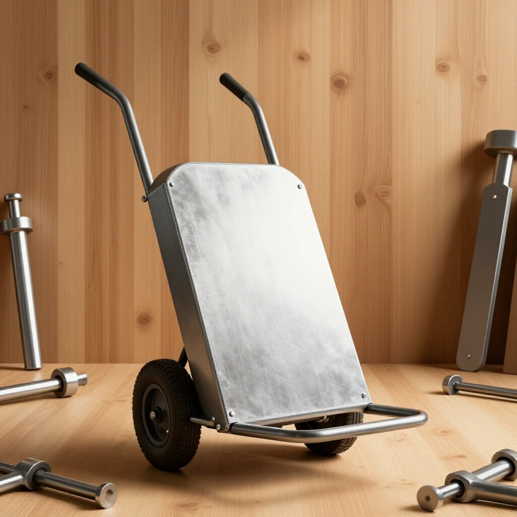
The nose plate is the flat steel tongue that slides under the machine. Many vintage tools have very low “feet” or solid cast bases that sit flush with the floor. A 3/16-inch plate with a tapered leading edge is ideal for sneaking under these tight spots without needing a pry bar.
I recommend a nose plate depth of 8 to 10 inches. Any deeper, and the leverage required to tilt the load becomes excessive. Any shallower, and the machine might slide off during transport. When building this, I often use a grinder to create a slight bevel on the front edge of the plate, making it easier to “kick” the dolly under a heavy base.
Restoring Salvaged Components for the Frame
Restoring classic cast iron often involves dealing with decades of “shop grime”—a mixture of oil, metal shavings, and rust. If you are using salvaged steel or old wheels for your transport device, you must strip them down to the base metal to ensure high-quality welds and smooth mechanical operation.
Removing machinery rust is a skill every restorer must master. For the steel components of our transport device, I prefer chemical chelators or electrolysis over aggressive grinding. Grinding removes the base metal and changes the dimensions of your parts. A chemical bath, however, only attacks the iron oxide, leaving the healthy steel intact for the fabrication process.
Chemical Rust Removal vs. Mechanical Grinding
Chemical rust removal involves soaking parts in a solution that breaks the bond between the rust and the metal. Mechanical grinding uses abrasives to physically wear away the rust. For precision parts like axles or bearing housings, chemical methods are always superior because they preserve the original tolerances of the metal.
| Method | Best For | Pros | Cons |
|---|---|---|---|
| Electrolysis | Large castings, heavy rust | Very cheap, reaches crevices | Requires DC power, messy |
| Evapo-Rust | Precision parts, axles | Non-toxic, preserves metal | Can be expensive for large parts |
| Wire Wheel | Flat steel, surface prep | Fast, easy to see progress | Doesn’t reach deep pits, dusty |
| Sandblasting | Large frames, non-precision | Extremely fast, creates “tooth” | Can warp thin metal, messy |
Using Electrolysis for Heavy Scale Removal
Electrolysis is a process that uses a 12V DC power source (like a manual battery charger) and a sacrificial anode to pull rust off a part. It is particularly effective for the heavy steel plate and brackets used in our shop transport device. I have used this method to clean everything from seized pulleys to entire drill press tables.
To set this up, fill a plastic tub with water and add one tablespoon of washing soda per gallon. Connect the negative lead to your steel part and the positive lead to a piece of scrap rebar (the anode). At 12V and about 2 to 10 amps, the rust will literally flake off over 12 to 24 hours. This leaves a clean, grey surface that is perfect for welding or painting.
Precision Axle Alignment and Bearing Service
A heavy-duty transport tool is only as good as its wheels. For a 600-pound load, pneumatic wheels are often preferred because they absorb the shock of cracks in the concrete. However, the axle and bearings are where most DIY builds fail. If the axle is not perfectly square to the frame, the dolly will “track” to one side, which is dangerous when moving heavy gear.
In vintage machinery restoration, we often deal with babbitt bearings or simple sleeve bearings. For our transport device, we will use a solid 5/8-inch or 3/4-inch steel rod as the axle. The fit between the axle and the wheel hub should be precise—ideally with a clearance of 0.001 to 0.002 inches. This prevents the wheels from wobbling, which can cause the load to shift unexpectedly.
Achieving 0.001-Inch Axle Tolerances
When you slide a wheel onto an axle, there should be no perceptible “clunk” or side-to-side play. If the axle is too small, the weight of the machine will cause the wheel to tilt, putting uneven pressure on the bearing. If I am using a salvaged rod that is slightly oversized, I will mount it in a lathe and use emery cloth to bring it down to the exact diameter needed.
If you don’t have a lathe, you can use a “poor man’s lathe” by spinning the rod in a drill press and holding the sandpaper against it. Use a micrometer to check your progress. We are looking for a “slip fit”—where the wheel slides on smoothly but doesn’t rattle. This precision ensures that even under a 600-pound load, the wheels turn with minimal friction.
Servicing Legacy Sleeve Bearings
Many high-quality wheels for shop use come with greaseable sleeve bearings. These are essentially tubes of bronze or hardened steel. Before assembling your transport device, check these for old, hardened grease. I often find that “frozen” wheels just need the old 1970s-era grease cleaned out with mineral spirits.
- Disassemble the wheel hub and remove the sleeve or roller bearings.
- Soak the bearings in a degreaser until all old lubricant is gone.
- Inspect the inner race for “pitting” or “brinelling” (small dents).
- Apply a high-pressure lithium grease before reassembly.
- Ensure the cotter pin or axle nut is tight enough to remove play but loose enough to allow free rotation.
Welding and Structural Assembly
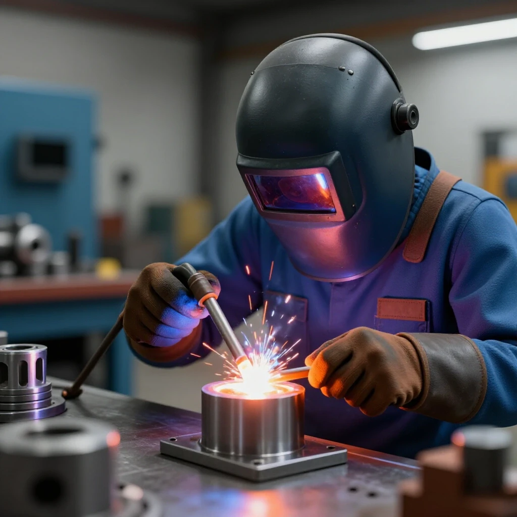
Welding the frame of your shop transport device is where the project truly takes shape. Because we are dealing with heavy loads, weld penetration is critical. I prefer MIG (Metal Inert Gas) welding for these projects because it provides a clean, strong bead that is easy to inspect. However, the sequence of your welds is just as important as the quality.
Heat causes metal to expand and contract. If you weld one side of the frame completely before starting the other, the heat will pull the frame out of square. In classic tool alignment, we talk about “tramming” or squaring the machine; the same logic applies here. Use magnets and heavy clamps to hold your 1.5-inch tubing at exactly 90 degrees before “tacking” the corners.
Managing Thermal Distortion During Fabrication
Thermal distortion occurs when the intense heat of the weld causes the steel to pull toward the joint as it cools. This can turn a perfectly square frame into a trapezoid. To prevent this, I use a “staggered” welding technique. I’ll place a small tack weld on the front left corner, then move to the back right, then the front right, and so on.
Once the frame is tacked and checked for squareness with a machinist’s square, I lay down the final beads in short 2-inch sections. This keeps the total heat in the metal lower. Interestingly, this is the same principle I use when straightening a warped cast-iron part: controlled heat and patience are your best friends.
Securing the Axle Brackets for Maximum Load
The axle brackets take the most abuse of any part of the device. They are the transition point between the static frame and the rolling wheels. Instead of just welding the axle directly to the frame, I use 3/16-inch steel “tabs” or brackets that are welded to the underside of the tubing.
This design allows the weight of the load to push “into” the weld rather than trying to “shear” it off. For maximum strength, I weld both the inside and outside of these brackets. After welding, I use a long straightedge to ensure both brackets are perfectly aligned. If they are off by even 1/8 of an inch, the dolly will be difficult to steer under a heavy load.
Finishing and Calibration for Shop Use
The final stage of any restoration or build is the finish. For a shop tool, paint isn’t just about aesthetics; it is about preventing the return of machinery rust. A high-quality primer and an oil-resistant enamel will protect your hard work from the spills and humidity common in a working shop.
Before painting, I always perform a “dry run” or a calibration check. I’ll load the device with something heavy—perhaps a spare engine block or a crate of sash weights—to see how the frame reacts. I look for any signs of flexing or “cracking” sounds in the welds. This is the same systematic approach I take when recalibrating the backlash in a vintage milling machine.
Surface Preparation for Oil-Resistant Finishes
Paint will not stick to steel that has even a microscopic film of oil. Since most new steel tubing comes with a protective oil coating (and our hands carry oils), a thorough degreasing is mandatory. I use a wax and grease remover or simple acetone.
- Wipe down the entire frame with a clean rag soaked in acetone.
- Apply a “self-etching” primer, which chemically bites into the steel.
- Follow with two coats of a heavy-duty machinery enamel (Safety Orange or Industrial Grey are classics).
- Allow the paint to cure for at least 48 hours before loading the device.
Testing and Precision Alignment
Once the paint is dry and the wheels are mounted, it’s time to check the “tracking.” Push the empty dolly across a flat section of your shop floor. It should roll in a perfectly straight line. If it veers to the left or right, one of your axle brackets is slightly out of alignment.
In the world of machinery hand scraping, we use “blueing” to find high spots on a surface. You can use a similar logic here to check wheel contact. If you roll the dolly through a small puddle of water and then onto dry concrete, the “tire tracks” should be parallel and of equal width. This confirms that the axle is square and both wheels are carrying an equal share of the weight.
Tracking Framework: The Machine Mover’s Checklist
To ensure your shop transport device is always ready for a rescue, I recommend keeping a small maintenance log. This is a habit I picked up from managing large machine shops, and it works just as well for DIY tools.
- Axle Inspection: Every six months, check for “grooving” on the axle rod.
- Tire Pressure: Pneumatic tires lose air over time. A soft tire can cause a 500-pound load to tip unexpectedly.
- Weld Check: Periodically wipe down the frame and look for “spider webbing” in the paint near joints, which indicates stress.
- Lubrication: Add a drop of 30-weight machine oil or a squeeze of grease to the wheel hubs after every heavy move.
- Fastener Tightness: Ensure the cotter pins or lock nuts holding the wheels are secure and haven’t been bent or sheared.
Final Thoughts on Shop Equipment Longevity
Building your own heavy-duty transport gear is more than just a weekend project; it is an exercise in engineering that prepares you for the complexities of vintage machinery restoration. By applying the same standards of precision—measuring in thousandths, understanding metallurgy, and respecting the physics of heavy loads—you create a tool that will last as long as the machines it carries.
The next time you see a “rust-bucket” lathe or a neglected drill press on a classifieds site, you won’t have to worry about the logistics of the rescue. You’ll have a custom-built, precision-aligned solution ready to roll. The key is to start with high-quality materials, take your time with the layout, and never compromise on the structural integrity of your welds.
Frequently Asked Questions
Why is 3/16-inch steel plate recommended over thinner 1/8-inch stock?
Thinner steel can flex under the concentrated “point loads” of heavy machinery feet. A 3/16-inch plate provides the necessary rigidity to prevent the nose of the dolly from bending downward, which would make it impossible to slide the tool back out from under the machine once moved.
Can I use solid rubber wheels instead of pneumatic ones?
Solid rubber wheels are excellent for very smooth shop floors and can carry higher weights without the risk of a flat. However, they offer no “cushion.” If your shop has expansion joints or uneven concrete, pneumatic tires are safer because they absorb the “jolt” that could otherwise tip a top-heavy machine.
How do I know if my welds have enough penetration for a 600-lb load?
A good weld should look like it is “sunk into” the metal rather than sitting on top of it. If the bead looks like a round “caterpillar” on the surface, you likely didn’t have enough heat. For 3/16-inch steel, you typically need a MIG welder set to around 18-20 volts.
What is the best way to prevent the axle from rusting to the wheel hub?
This is a common “seized part” issue. Before assembly, coat the axle rod with a thin layer of “anti-seize” lubricant or a heavy marine-grade grease. This creates a moisture barrier that prevents the galvanic corrosion often seen in shop environments.
How do I balance a machine that is much wider than the dolly?
When moving wide machines, use heavy-duty ratcheting straps to secure the machine’s column to the vertical frame of the dolly. This makes the machine and the transport device a single “unit,” preventing the machine from sliding sideways during a turn.
Is it necessary to use a machinist’s square for a simple cart?
Yes. If the frame is even one degree out of square, the load will not sit flat on the nose plate. This creates “twisting” forces on the frame that can lead to weld failure over time. Precision at the start prevents structural fatigue later.
What should I do if I find a crack in a salvaged cast-iron wheel?
Do not attempt to weld a structural crack in a cast-iron wheel unless you are experienced with pre-heating and nickel-rod welding. Cast iron is brittle, and a failed wheel under a 500-pound load is a major safety hazard. It is always safer to replace a cracked wheel with a new steel or heavy-duty poly-on-cast-iron version.
Why is the axle offset 5-6 inches from the frame?
This offset creates the “fulcrum” needed to lift the load. If the axle were directly under the frame, you would have no leverage to tilt the machine back. The 5-6 inch gap allows the machine’s center of gravity to move over the wheels, making the load feel balanced and manageable.
(This article was written by one of our staff writers, Richard Beaumont. Visit our Meet the Team page to learn more about the author and their expertise.)