How to Build a Protected Wall Rack for Calipers and Mic (Fix)
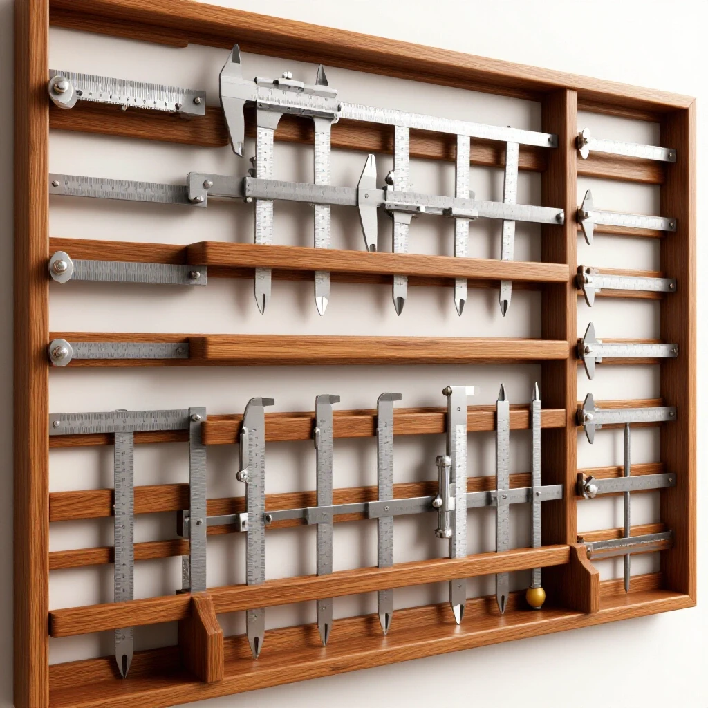
I have spent over a decade in prototype shops and home garages, and if there is one thing I have learned, it is that precision tools like calipers and micrometers do not belong on a cluttered workbench. I still remember the sinking feeling of watching a pair of expensive digital calipers slide off a table and hit the concrete floor. It was that moment, years ago, that drove me to start building dedicated, heavy-duty metal enclosures for my most sensitive gear. In this guide, I will walk you through the process of fabricating a wall-mounted protective unit designed to keep your measurement tools safe from dust and impact.
Building a custom fabrication project like this requires more than just sticking metal together. You have to account for the physics of the material. When you apply heat to thin sheet metal or small square tubing, it wants to move. I have seen many well-intended projects turn into a twisted mess because the builder did not plan for weld shrinkage or thermal expansion. We are going to focus on maintaining tight tolerances, often within a +/- 1/16th inch margin, to ensure the finished enclosure is square, functional, and professional.
Planning the Layout and Material Selection for Precision Tool Housing
Designing the blueprint and selecting materials for a tool enclosure requires balancing structural rigidity with weight. By choosing specific gauges of steel and planning for the exact footprint of your calipers and micrometers, you create a foundation that prevents sagging and ensures every precision instrument has a secure, dust-free home.
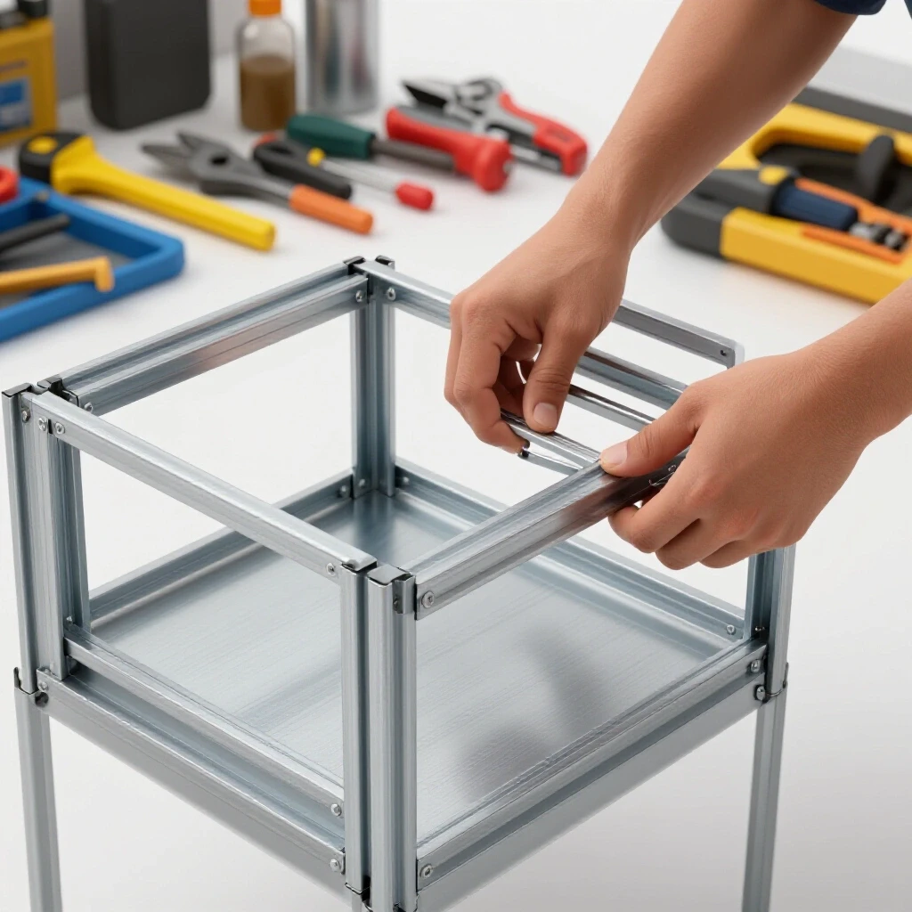
When I start a project like this, I lean toward 16-gauge (0.0598 inch) mild steel sheet for the main body. It is thick enough to provide a solid shield against workshop hazards but light enough that you can mount it to a standard wall stud without over-engineering the bracketry. If you prefer a framed look, 1/2-inch square tubing with a 0.065-inch wall thickness works exceptionally well for the skeleton.
Before you pull the trigger on your plasma cutter or chop saw, lay out every tool you intend to house. I recommend leaving at least 1/2 inch of clearance around each tool to allow for easy access with gloved hands. For a standard 6-inch caliper and a set of 0-3 inch micrometers, a cabinet measuring 18 inches wide by 12 inches tall is usually a safe bet. I always document these dimensions in a formal cut list to track my material yield and minimize waste.
Calculating Kerf Allowances and Accurate Cutting Strategies
Kerf is the material lost during the cutting process, typically ranging from 1/16 to 1/8 of an inch depending on the tool. Mastering kerf calculation is the first step in custom fabrication, as it ensures that your final frame dimensions match your blueprints exactly after the pieces are joined.
If you are using an abrasive chop saw, your kerf might be as wide as 3/32 of an inch. If you ignore this, and you have four joints in a frame, your enclosure could end up nearly half an inch shorter than you planned. I prefer using a cold saw or a high-quality bandsaw for these projects because the kerf is more predictable, usually around 0.040 to 0.060 inches.
| Cutter Type | Typical Kerf Width | Dimensional Accuracy | Best Use Case |
|---|---|---|---|
| Abrasive Saw | 0.090″ – 0.125″ | Low | Rough structural cuts |
| Band Saw | 0.035″ – 0.050″ | High | Precision frame parts |
| Plasma Cutter | 0.040″ – 0.080″ | Medium | Sheet metal shapes |
| Laser/Waterjet | 0.005″ – 0.015″ | Extreme | High-tolerance prototypes |
When marking your steel, use a fine-point scribe instead of a thick carpenter’s pencil. A pencil line can be 1/32 of an inch wide on its own. By scribing a crisp line and cutting on the “waste side” of that line, you maintain the integrity of your measurements. This is especially important when you are building the internal tracks where the calipers will rest.
Designing Workshop Jigs to Maintain Square Alignment
Workshop jigs act as a rigid skeleton that holds your metal pieces in place during the assembly phase. Using fixtures like magnetic squares or heavy-duty corner clamps prevents the frame from shifting as you apply heat, maintaining the tight dimensional tolerances required for a professional-grade workshop storage solution.
I never trust a magnet alone to keep a project square during welding. Magnets are great for the initial “mock-up,” but the moment you strike an arc, the cooling weld bead will exert hundreds of pounds of force. To combat this, I build simple corner jigs using scrap 2×2 angle iron. I weld two pieces of angle iron at a verified 90-degree angle to create a “pocket” where my enclosure corners can sit.
During the assembly of the outer shell, I use C-clamps to lock the sheet metal against these jigs. This physical restraint is the only way to ensure that the enclosure does not “diamond” or twist. If you are working on a flat welding table, use 1-2-3 blocks to verify that your vertical walls are perfectly perpendicular to the base.
- Jig Spacing: Place a clamp every 4 to 6 inches along a joint.
- Verification: Use a machinist’s square to check the internal corners after clamping but before tacking.
- Stability: Ensure your jig is heavy enough that it does not warp from the heat transferred from the workpiece.
Tack Welding Techniques and Proper Sequencing
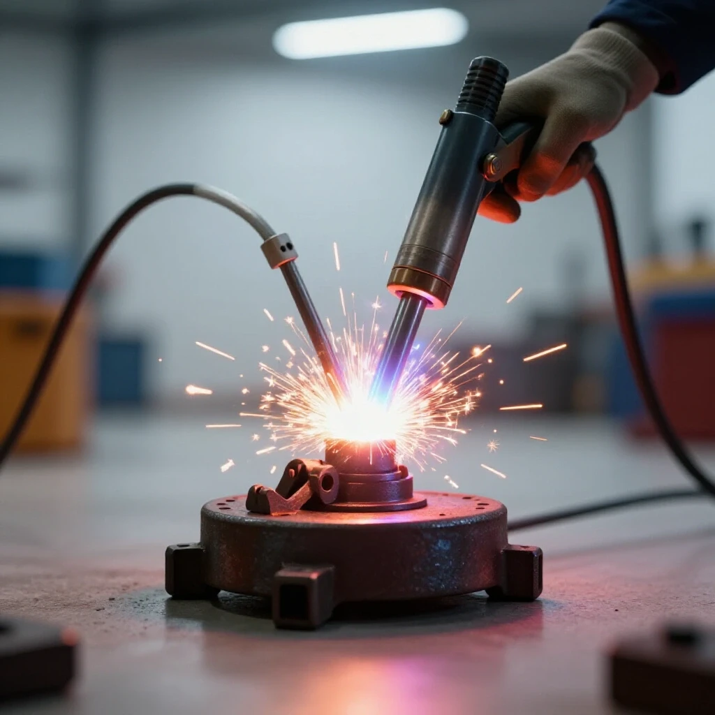
Tack welding is the process of using small, localized beads to lock your assembly into position before final welding. Strategic tack placement is essential for controlling the “pull” of the metal, ensuring that your enclosure remains square and true even as the intense heat of the arc is applied.
In my early years as a technician, I made the mistake of welding a full seam from one end to the other. By the time I reached the end, the metal had pulled the corner in by 1/8 of an inch. Now, I follow a strict tacking sequence. For a 12-inch seam, I place a tack at both ends, then one in the middle, and then fill in the gaps until I have a tack every 2 inches.
Each tack should be small—roughly the size of a pencil eraser. If a tack is too large, it becomes a permanent part of the structure that is hard to weld over smoothly. If it is too small, it will “pop” when the metal begins to move. I use a TIG welder for these enclosures because it offers the most control over the heat-affected zone (HAZ), but a MIG welder with a fast trigger finger works just as well for garage builds.
Managing Thermal Distortion and Weld Shrinkage
Thermal distortion is the inevitable movement of metal caused by the heating and cooling cycles of welding. By understanding how weld shrinkage forces work and using techniques like backstepping or heat sinks, you can manage these physical changes to keep your protective tool housing from warping into an unusable shape.
When you weld, the molten metal expands. As it cools, it contracts more than it expanded, creating a “pulling” force toward the weld. To counter this on the flat panels of your tool enclosure, you can use aluminum or copper heat sinks. Placing a thick bar of aluminum behind your weld joint helps soak up the excess heat, which reduces the size of the heat-affected zone and limits warping.
Another technique I rely on is backstepping. Instead of welding from left to right in one long bead, you weld in short segments from right to left, moving your starting point progressively forward. This distributes the heat more evenly across the panel.
| Technique | How it Works | Primary Benefit |
|---|---|---|
| Backstepping | Welding in short, reverse segments | Even heat distribution |
| Heat Sinking | Using copper/aluminum backing | Reduces heat-affected zone |
| Skip Welding | Jumping between different corners | Prevents localized overheating |
| Pre-bending | Angling parts slightly “out” before welding | Compensates for inward pull |
Fabricating Internal Dividers and Secure Mounting Points
The final assembly phase involves creating customized internal slots for your instruments and preparing the enclosure for wall attachment. Proper divider placement protects the delicate surfaces of your tools, while reinforced mounting holes ensure the heavy steel unit remains stable and level once it is installed in your shop.
For the internal dividers, I use 20-gauge steel strips or even thick rubber-lined aluminum. These dividers should be spot-welded or riveted into place. I prefer rivets for the interior because they do not require high heat, which means you won’t warp the outer shell you just worked so hard to keep square. I often line the bottom of each slot with adhesive-backed felt or closed-cell foam to give the calipers a soft place to land.
Over time, the weight of the steel and the tools can cause the thin metal to “oil-can” or pull away from the wall. I weld a 1/8-inch thick flat bar across the top and bottom of the back panel. This acts as a mounting flange. Drill your holes through this thicker bar at 16-inch centers so you can bolt directly into the wall studs.- Mounting Hardware: Use 1/4-inch lag bolts or heavy-duty structural screws.
- Internal Padding: Use 1/16-inch felt to prevent scratches on micrometer frames.
- Finishing: De-burr every edge with a flap disc to ensure there are no sharp burrs that could cut your hands or damage your tools.
Final Alignment Checks and Finishing Touches
Before you call the project finished, you must perform a final alignment check. I use a straightedge to ensure the back panel is flat. If there is a slight bow, you can sometimes “cold-straighten” it with a rubber mallet and a block of wood, but be careful not to dent the surface.
For the finish, a simple coat of industrial enamel or powder coating is best. Avoid heavy textured paints inside the enclosure, as they can trap grinding dust and metal shavings—the very things you are trying to keep away from your precision instruments. A smooth, semi-gloss finish is easier to wipe down and keep clean.
Actionable Fabrication Framework
- Cut List: 16ga sheet for body, 1/8″ flat bar for mounting, 20ga for dividers.
- Layout: Scribe lines with a +/- 1/32″ tolerance.
- Fixturing: Clamp to a heavy jig or welding table.
- Tacking: Space tacks at 2-inch intervals, alternating sides.
- Welding: Use backstepping and allow the metal to cool to the touch between passes.
- Dividers: Install using rivets or small tacks to minimize distortion.
- Mounting: Verify 16-inch centers for stud alignment.
Building a custom, protective home for your tools is a rite of passage for any serious fabricator. It teaches you how to respect the material and how to plan for the forces that want to pull your work out of square. When you hang that enclosure on the wall and slide your calipers into their custom slots, you will know they are safe, and you will have a piece of shop furniture that reflects your skill as a builder.
Frequently Asked Questions
Why did my enclosure frame twist even though I used magnets? Magnets provide very little resistance against the mechanical force of a cooling weld. As the weld pool solidifies, it shrinks and pulls the metal. You must use mechanical clamps and rigid jigs to physically restrain the parts until the welds have cooled completely.
Can I use thinner metal, like 22-gauge, to save weight? I don’t recommend it for a wall-mounted unit. Thinner metal is much harder to weld without blowing through, and it warps significantly faster. 16-gauge or 18-gauge provides the right balance of durability and weldability for a garage environment.
What is the best way to prevent the internal dividers from rattling? Using a small bead of silicone or adhesive-backed foam along the edges of the dividers before securing them will dampen vibrations. If you are welding them, ensure you have at least three small tacks per side to keep them rigid.
How do I handle “pull” when welding the corners? Try “preset” your corners. If you know the weld will pull the joint inward by 1 or 2 degrees, you can clamp the joint so it is slightly “open” (more than 90 degrees). When the weld cools, it will pull the joint into a square 90-degree angle.
Should I use MIG or TIG for this project? TIG is superior for thin sheet metal because you can control the heat input independently of the filler metal. However, MIG is much faster. If using MIG, use a “stitch” technique—short bursts of trigger pulls—to keep the heat down.
How do I ensure the door (if added) fits perfectly? Always build the enclosure body first, then measure the actual opening. Do not rely on your original blueprints for the door dimensions, as the body may have shrunk or expanded slightly during welding. Aim for a 1/8-inch gap around the door perimeter.
What is the best way to clean the metal before welding? Use a flap disc or a wire wheel to remove all mill scale and oil from the weld zones. Contaminated metal leads to porous welds, which are weaker and more likely to crack under the stress of thermal contraction.
How can I make the enclosure dust-proof? Incorporate a small lip or flange around the opening where the door meets the body. You can apply a thin strip of automotive weatherstripping to this flange to create a seal that keeps out fine grinding dust and moisture.
Why is my sheet metal “oil-canning” (popping in and out)? This is caused by localized heat expansion. The center of the panel expanded from the heat, but the edges were held rigid by the frame. To fix this, you may need to add a small stiffener or “cross-break” the panel by bending a slight “X” shape into it before assembly.
What mounting height is best for a wall-mounted tool rack? I recommend mounting it at eye level, typically 60 to 65 inches from the floor. This allows you to read the scales on your tools without removing them from the rack and keeps them out of the “splash zone” of sparks from floor-level grinding.
(This article was written by one of our staff writers, Robert Kline. Visit our Meet the Team page to learn more about the author and their expertise.)