How to Organize and Label Multi-Component Batch Runs (Guide)
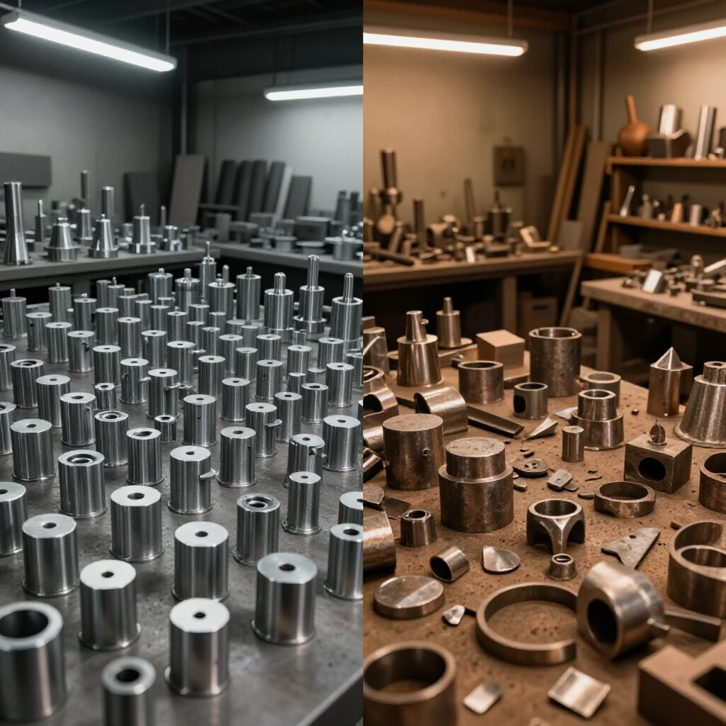
I have spent more than twenty years navigating the transition from a cluttered garage setup to a high-output fabrication facility. The most painful lesson I learned during that time was that cutting speed means nothing if you cannot find the parts you just finished. When you move from making one-off projects to managing dozens of identical components, the physical chaos can quickly overwhelm your floor space. Scaling a shop requires a shift in mindset from “craftsman” to “operations manager,” where every square foot of concrete and every amp of power must be justified by its contribution to throughput.
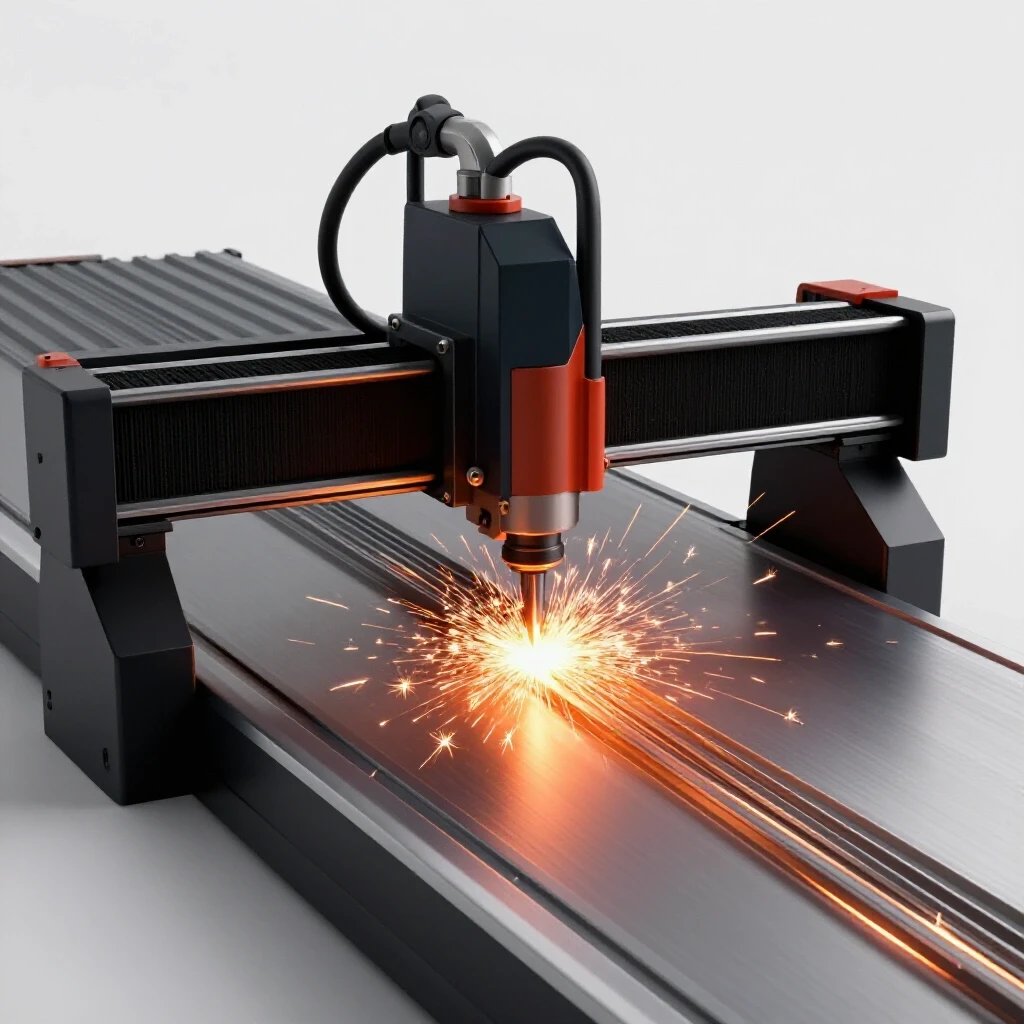
The stress of scaling often comes from the sudden realization that your old ways of working do not stretch. You might have a new CNC plasma table that can cut fifty brackets in twenty minutes, but if those brackets end up in a pile on the floor, you have created a bottleneck, not a solution. My goal is to share the systems I have used to reorganize my own shop, focusing on the physical infrastructure and manual tracking methods that keep a professional-grade workshop running smoothly without the need for complex digital overhead.

Mapping Material-Flow Loops to Prevent Shop Bottlenecks
Material-flow mapping is the process of documenting the physical path a piece of raw stock takes from the delivery truck to the final shipping crate. It involves identifying every stop, turn, and storage point to minimize unnecessary movement and handling time within the shop.
In my early years, I spent half my day moving sheets of steel just to get to the one I needed. This is what lean manufacturing calls “waste of motion.” To fix this, I began using a spaghetti diagram. I took a printout of my shop floor plan and drew a line for every step I took during a typical production run. The result looked like a tangled mess of yarn. By identifying where those lines crossed or doubled back, I could see exactly where my layout was failing me.
Building an efficient flow requires a linear or U-shaped pattern. Raw material should enter near your primary cutting station, such as a CNC plasma table or a horizontal band saw. From there, parts should move in one direction toward deburring, then to secondary machining, and finally to assembly or coating. If a part ever travels backward against the flow, you are losing money. I recommend a minimum of 3 feet of clearance for all primary travel paths to allow for carts and pallet jacks to pass without snagging on machinery.
Building a Reliable 3-Phase Power Backbone for Heavy Machinery
A 3-phase power system provides three alternating currents that are out of phase with each other, delivering more consistent torque and higher efficiency for industrial motors. For home-based shops, this usually requires a phase converter to transform standard single-phase residential power into the 3-phase power needed for heavy-duty fabrication equipment.
Most advanced shops eventually hit a wall with 240V single-phase power. When I added my first industrial-grade mill and a high-capacity air compressor, I had to choose between a rotary phase converter (RPC) and a variable frequency drive (VFD). An RPC uses a 3-phase motor as a generator to create the third leg of power. It is a workhorse that can power multiple machines at once, but it is loud and consumes electricity even when the machines are idling.
VFDs are excellent for single-machine setups because they offer speed control and a soft start, which protects your motors. However, for a shop running a batch of components across several stations, a large rotary converter is often the most practical choice. I aim for a voltage balance within 5% between all three legs. If the voltage on the manufactured leg drops too low under load, your motors will run hot and eventually fail.
| Converter Type | Best Use Case | Efficiency | Complexity |
|---|---|---|---|
| Static Converter | Starting a motor only; low power | Low | Low |
| Rotary Phase Converter | Multiple machines; high-torque loads | Medium-High | Medium |
| Variable Frequency Drive | Single machine; precision speed control | High | High |
| Digital Phase Converter | Highly sensitive CNC electronics | Very High | High |
Designing High-Volume Air Filtration and Fume Extraction
High-volume air filtration involves moving a specific volume of air, measured in Cubic Feet per Minute (CFM), through a series of filters or collectors to remove hazardous dust and fumes. This system must account for static pressure, which is the resistance the air faces as it moves through ducts and filters.
When I integrated a CNC plasma table, the smoke was unbearable within minutes. I quickly learned that a standard shop vac or a small ceiling-mounted air scrubber was useless. For a 4×8 plasma table, you need an extraction system capable of moving at least 1,500 to 2,000 CFM. If your ductwork is too small or has too many 90-degree bends, the static pressure will skyrocket, and your actual airflow will plummet.
I suggest using smooth-walled metal ducting rather than flexible ribbed hoses for your main runs. Every foot of flexible hose has about three times the resistance of smooth pipe. I also installed a multi-stage cyclone separator. This pulls the heavy dust and sparks out of the air before they reach the expensive fine filters. It saved me a fortune in filter replacements and kept the shop floor significantly cleaner during long production cycles.
Integrating CNC Plasma Systems into a Production Workflow
CNC plasma integration is the process of adding an automated cutting table into your shop and aligning its output with your manual fabrication steps. This requires leveling the machine gantry, calibrating torch height controllers, and organizing the nesting of parts to maximize material usage.
The biggest hurdle I faced with automation was not the machine itself, but the “hurry up and wait” syndrome. The CNC table would finish a sheet of fifty parts, and I would have no place to put them. To solve this, I built dedicated offload tables at the same height as the plasma slats. This allows me to slide the entire skeleton off the machine and start the next sheet immediately.
Leveling your gantry is a task you only want to do once, so take your time. Use a precision machinist’s level and check for squareness across the entire 8-foot travel. If the table is out of level by even a fraction of an inch, your torch height control will struggle, leading to inconsistent cuts and wasted material. I also recommend keeping a log of “cut recipes”—specific settings for amperage, speed, and air pressure for every material thickness you run. This eliminates the guesswork during setup.
Managing Physical Part Sorting and Identification for Batch Production
Physical part sorting is the systematic organization of cut components into designated containers to ensure that no items are lost or mixed up during the manufacturing process. This involves using bins, trays, and physical markers to maintain order as parts move through different stages of fabrication.
When you are running a batch of several hundred components, organization is your best friend. I use a “bin and tag” system. Every unique part number gets its own dedicated bin. Before I even start the CNC table, I prepare a stack of physical tags. Each tag lists the part name, the quantity required, and the next step in the process, such as “Deburr” or “Bend.”
Interestingly, color-coding these bins can drastically reduce errors. I use green bins for parts that are ready for the next stage and red bins for parts that need rework or have failed inspection. This visual cue allows me to see the status of a project from across the room. It prevents the common mistake of a finished part accidentally being tossed back into the scrap pile or a raw part being sent to the assembly bench prematurely.
- Use heavy-duty plastic bins that can be stacked when empty to save floor space.
- Attach magnetic label holders to metal bins for easy updates.
- Include a “Master Part List” on a clipboard at the start of the line to track total progress.
- Ensure every bin has a clear physical separation to prevent parts from migrating.
Implementing Shop-Floor Tracking Systems Without Digital Software
A shop-floor tracking system is a manual method of monitoring the progress of a job through various work centers. It relies on physical documents, such as travelers or checklists, that follow the material as it is transformed from raw stock into a finished product.
I have found that paper-based “travelers” are often more reliable in a gritty shop environment than a tablet or computer. A traveler is a single sheet of paper that stays with a batch of parts from start to finish. It contains the drawing, the step-by-step instructions, and a space for a signature or initials after each task is completed. This creates accountability and ensures that no steps, like a critical hole deburring, are skipped.
To make this work, I set up a central “Job Board” near the main workbench. This board has hooks for every active project. When I finish a batch of parts at the plasma table, I move the traveler to the “Secondary Ops” hook. This gives me a high-level view of where every project stands without having to count individual parts. It also helps me identify which station is currently the bottleneck. If the “Bending” hook has five travelers on it and the “Welding” hook is empty, I know where I need to focus my energy for the afternoon.
Actionable Tracking Frameworks and Safety Checklists
To maintain a professional-grade operation, you need consistent repeatable processes. I use a series of checklists to ensure that nothing is overlooked during the transition from a quiet shop to a full production run. These checklists are laminated and posted directly at the machines.
-
Pre-Flight CNC Checklist:
- Check air compressor for moisture and drain tanks.
- Verify torch consumables (nozzle and electrode) for wear.
- Clear the table slats of any tip-ups from previous runs.
- Zero the X, Y, and Z axes at the starting corner.
- Confirm the material thickness matches the software settings.
-
Batch Run Verification:
- Count the first five parts to verify dimensions against the drawing.
- Check for excessive dross or taper on the cut edges.
- Place parts immediately into the labeled bin.
- Update the traveler with the quantity of good parts produced.
-
End-of-Day Shop Reset:
- Empty the slag tray under the plasma table.
- Blow off the gantry rails and apply a light coat of dry lubricant.
- Clean the primary filters on the air extraction system.
- Organize all bins on the “Work in Progress” shelving unit.
Optimizing Floor Space for Multi-Part Assembly
Floor space optimization is the strategic placement of equipment and work surfaces to maximize the usable area for assembly and material handling. This often involves using mobile bases for machinery and creating flexible workspaces that can be reconfigured based on the project size.
In a small-scale shop, every inch counts. I put almost everything in my shop on heavy-duty locking casters. This allows me to push the welding tables together for a large assembly or spread them out to create separate work cells for a multi-component run. I also utilize vertical space by building high-capacity racks for my sorting bins.
One of the most effective changes I made was the “3-foot rule.” I ensured that every stationary machine has at least 3 feet of clear space around it for maintenance and operator movement. This prevents that cramped feeling that leads to fatigue and mistakes. When you are handling large batches of heavy steel parts, having room to move safely is a matter of both efficiency and safety.
| Machine | Required Clearance | Power Needs | Air/Ventilation |
|---|---|---|---|
| CNC Plasma Table | 4 feet (loading side) | 240V / 50A | 2,000 CFM Extraction |
| Horizontal Band Saw | 6 feet (infeed/outfeed) | 120V or 240V | Minimal |
| 50-Ton Press Brake | 3 feet (all sides) | 3-Phase / 20A | None |
| Welding Station | 5 feet (work area) | 240V / 50A | Fume Arm / 800 CFM |
Strategies for Successful System Commissioning
System commissioning is the final stage of an upgrade where you test every component of a new setup under real-world conditions. This process identifies flaws in the layout, electrical balance, or workflow before you commit to a high-volume production schedule.
When I finished my last major shop overhaul, I didn’t immediately start a 500-part order. Instead, I ran a “pilot batch” of five units. This allowed me to see how the parts moved from the plasma table to the deburring station and then to the bins. I realized that my deburring station was too far from the plasma table, causing me to walk an extra 400 feet over the course of the pilot run. I moved the station, and that small change saved me hours of walking over the next month.
Always monitor your electrical system during commissioning. I used a clamp-on ammeter to check the load on my phase converter while the compressor and the CNC table were running simultaneously. I found that I was nearing the limit of my main breaker, which allowed me to adjust my schedule so that the heavy-draw machines didn’t all fire up at the same time. This kind of data-driven decision-making is what separates a professional operation from a hobbyist setup.
Frequently Asked Questions
How do I handle parts that look identical but have slight variations? I use color-coded physical tags or different colored bins for parts that are visually similar but functionally different. For example, left-hand and right-hand brackets go into blue and yellow bins respectively. Never rely on your memory to distinguish between parts with a 1/8-inch difference in hole placement.
What is the best way to label parts that will be powder coated or painted? For parts going to coating, avoid using permanent markers or adhesive stickers, as these can be difficult to remove or may bleed through the finish. I use metal stamped tags attached with wire or heat-resistant hang tags. If the parts are large enough, I sometimes use a center punch to make a small, discreet mark that indicates the part number.
How much should I spend on a 3-phase converter for a home shop? A quality rotary phase converter for a typical micro-manufacturing setup usually costs between $1,500 and $3,000. While this is a significant investment, it is often cheaper than paying the utility company to drop a dedicated 3-phase line to a residential or light-commercial building, which can cost upwards of $10,000.
Is a water table or a downdraft table better for CNC plasma fume control? A water table is generally more affordable and does a great job of trapping sparks and heavy dust. However, a downdraft table with a high-CFM blower is often more effective at removing the fine, airborne smoke that can linger in a shop. For high-volume batch runs, I prefer a downdraft system because it keeps the parts dry and ready for the next step.
How do I calculate the CFM needed for my shop’s air filtration? A good rule of thumb is to aim for 6 to 8 air exchanges per hour. Calculate the total volume of your shop (length x width x height) and multiply by the number of exchanges, then divide by 60. For local extraction at a machine, you need enough velocity at the source to capture the dust before it escapes, usually 1,000 to 2,000 CFM for a plasma table.
What is the most common mistake when reorganizing a shop layout? The most common mistake is failing to account for material handling. People often place machines based on where the electrical outlets are, rather than where the metal needs to go. Always prioritize the flow of material first, then move the electrical and air lines to support that flow.
How do I keep track of quantities without using a computer? I use a physical “tally sheet” attached to each bin. Every time I drop a finished part into the bin, I make a mark. Once I hit a predetermined number (like 10 or 25), I circle the marks. This makes it very easy to see at a glance how close I am to finishing a batch without having to recount the entire pile.
What are the signs that my shop has outgrown its current layout? If you find yourself moving one object to get to another more than three times a day, your layout is failing. Other signs include “dead zones” where scrap and half-finished projects pile up, or if your walking paths are consistently blocked by pallets or carts.
Can I run a CNC plasma table on a static phase converter? I would not recommend it. Static converters only provide 3-phase power during the start-up of a motor and then drop back to single-phase. CNC electronics and the high-frequency starts of a plasma cutter require the stable, balanced power that only a rotary or digital converter can provide.
How often should I maintain my dust collection system? In a high-output shop, you should check your primary filters and empty the collection bins weekly. Once a month, check the ductwork for any heavy buildup or clogs, especially near bends. Replacing filters before they are completely choked will save wear and tear on your blower motor.
What is “static pressure” and why does it matter for my vacuum system? Static pressure is the resistance to airflow. Think of it like trying to breathe through a straw. The longer the straw or the more bends it has, the harder it is to pull air through. If your static pressure is too high, your 2,000 CFM blower might only be moving 800 CFM at the machine, leaving the shop full of dust.
How do I ensure my CNC parts are consistent across a long batch run? Check your consumables every 50 to 100 pierces. A worn nozzle will cause the arc to wander, leading to tapered edges and dimensional errors. I also recommend a “mid-run” check where you measure a part halfway through the batch to ensure the machine hasn’t lost steps or shifted.
(This article was written by one of our staff writers, Edward Sinclair. Visit our Meet the Team page to learn more about the author and their expertise.)