How to Set Up and Align Milling Machine Fixtures Fast (Fix)
The transition from a hobbyist workspace to a professional-grade fabrication environment is often marked by a shift in how you value time. In my twenty years of operating a home-based shop, I have learned that the most significant losses occur not during the actual cutting of metal, but in the minutes wasted between tasks. When I first integrated a CNC plasma system into my workflow, I realized my manual milling station was becoming a massive bottleneck. The struggle wasn’t the machine itself, but the time it took to get workholding secured and squared accurately enough to match the precision of my newer automated tools.
Scaling a business requires a systematic approach to every square foot of your floor plan. If you are constantly fighting to find a dial indicator or struggling to square a vise on a table that hasn’t been properly leveled, you are losing money. I found that by applying lean manufacturing principles—originally designed for massive factories—to my small-scale setup, I could drastically reduce setup times. This guide focuses on the technical nuances of preparing your milling station for rapid transitions, ensuring your manual operations keep pace with your shop’s growth.
Mapping Material-Flow Loops to Minimize Shop Bottlenecks
Material-flow loops are the physical paths raw stock takes from delivery to the milling station and eventually to shipping. Mapping these loops helps identify backtracking and wasted movement, ensuring that your workholding setup is the only thing you are focusing on once the material arrives at the machine.
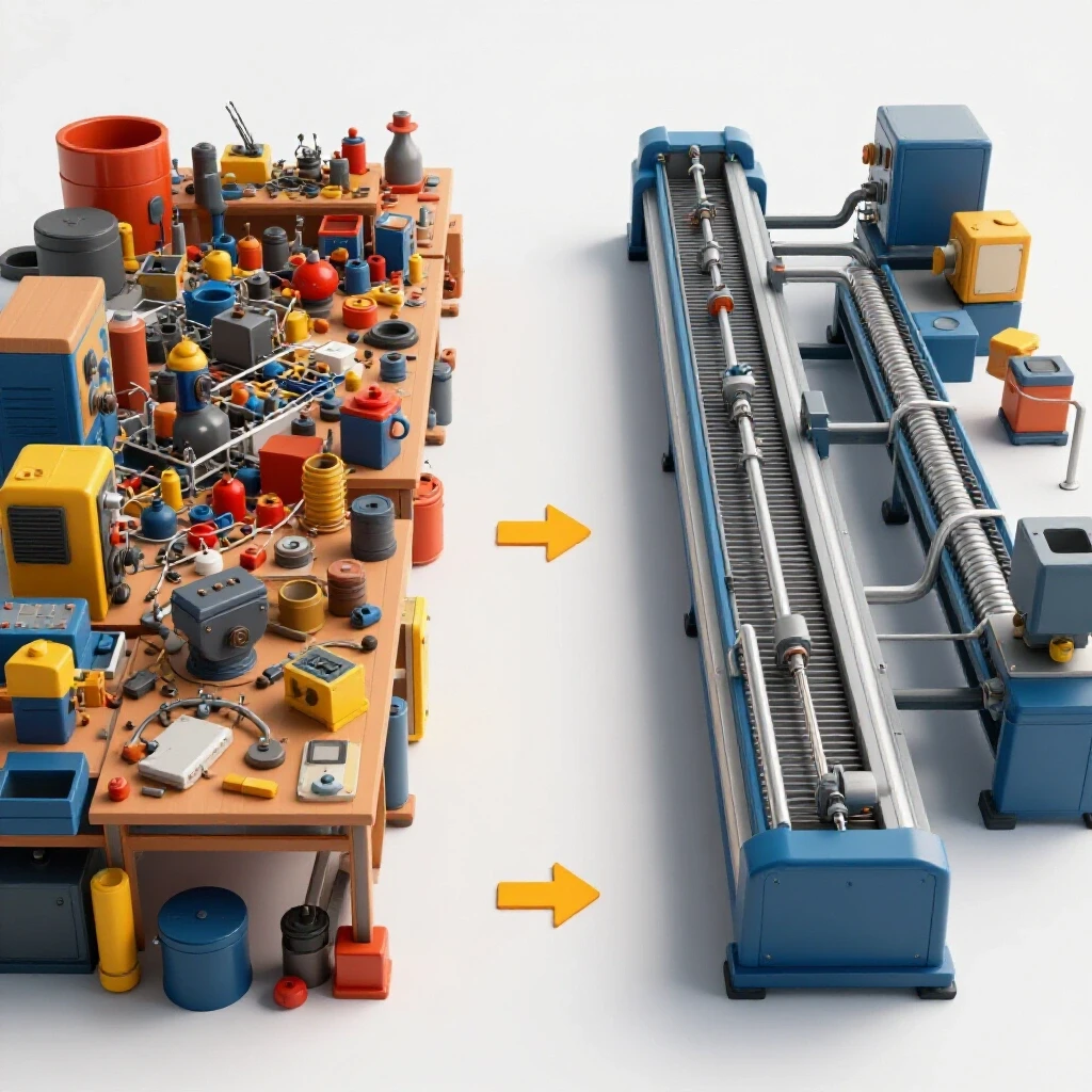
In my early years, I had my material rack at one end of the shop and my mill at the other. Every time I needed to square a block, I walked fifty feet. When you are scaling, these steps add up to hours of lost production every month. I eventually redesigned my layout to follow a linear flow: raw material enters, moves to the saw, then to the mill for secondary operations, and finally to the assembly or shipping area.
Effective flow management also involves the “three-foot rule.” I maintain a minimum of three feet of clear access around every machine. This isn’t just for safety; it allows you to move parts and tools without shuffling other items out of the way. When your milling station is clear of clutter, the process of positioning your workholding becomes a focused, five-minute task rather than a twenty-minute ordeal of clearing space.
| Layout Type | Flow Efficiency | Space Requirement | Best Use Case |
|---|---|---|---|
| U-Shaped | High | Medium | Single-operator micro-manufacturing |
| Linear (I-Flow) | Very High | Low/Narrow | Long, narrow garage or shop spaces |
| Cellular | Extreme | High | Dedicated production of specific parts |
| Random | Very Low | Variable | Hobbyist/General repair shops |
Rapid Techniques for Squaring Milling Vises and Fixtures
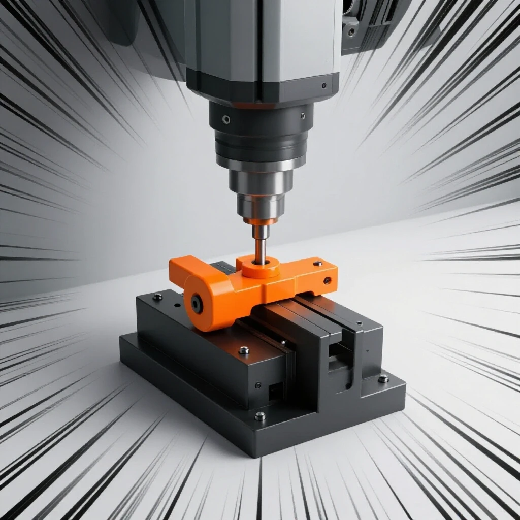
Squaring a vise involves aligning its fixed jaw perfectly parallel to the machine’s longitudinal axis. By using a dial indicator and a systematic approach to tightening mounting bolts, you can achieve alignment within 0.0005 inches in a matter of minutes, which is essential for maintaining accuracy across multiple parts.
I remember the frustration of chasing the “zero” on a dial indicator for thirty minutes. The mistake most of us make is tightening the bolts too early. I start by placing the vise on the table and lightly snugging one bolt. I then place the dial indicator on the spindle and bring the tip against the fixed jaw. By moving the table along the X-axis, I can see exactly which way the vise needs to pivot.
Interestingly, the “tap and check” method is the fastest way to correct errors. Instead of loosening everything, I use a dead-blow hammer to gently nudge the vise while the indicator is under slight tension. Once the needle stays still across the full length of the jaw, I tighten the bolts in a crisscross pattern. This prevents the act of tightening from pulling the fixture out of alignment, a common issue that causes many fabricators to start over.
- Clean the table and the bottom of the vise thoroughly to remove any chips.
- Stone the table surface to remove small burrs that could tilt the fixture.
- Use a high-quality dial indicator with at least 0.0005-inch graduations.
- Always indicate off the fixed jaw, never the movable jaw.
- Tighten bolts in increments, checking the alignment at each stage.
Building Balanced 3-Phase Power Systems for Consistent Torque
3-phase power delivery provides the consistent torque required for heavy milling operations. For shops without utility 3-phase, using rotary phase converters or Variable Frequency Drives (VFDs) ensures your milling machine maintains spindle speed under load, preventing fixture shifts during aggressive cuts.
When I upgraded to a larger vertical mill, I was faced with a common problem: my shop only had single-phase 240V power. I had to decide between a Rotary Phase Converter (RPC) and a VFD. While VFDs are excellent for speed control, a well-sized RPC can power multiple machines simultaneously. I chose a 10HP rotary converter to handle my mill and a future surface grinder.
The key to a reliable 3-phase setup is voltage balance. If the manufactured third leg of power is more than 10% different from the others, your motor will run hot and lose torque. I use a digital multimeter to check the legs under load. Consistent power means the machine doesn’t vibrate or “chatter” as much, which directly impacts how well your workholding stays put during heavy milling.
- Calculate the total horsepower of all machines that might run at once.
- Size the converter at least 50% larger than the largest motor to handle startup surges.
- Install a dedicated sub-panel for 3-phase distribution to keep the shop organized.
- Use proper wire gauges based on the National Electrical Code (NEC) to prevent voltage drop.
- Balance the legs using capacitors if the voltage spread exceeds 5%.
Optimizing Air Quality and Dust Collection Near Machining Centers
Air quality management involves removing fine particulates and oil mist generated during the milling process. High-volume filtration systems and targeted collection hoods prevent the buildup of grime on machine ways and fixtures, which can interfere with the precision of your alignments over time.
In my shop, I noticed that my precision tools were starting to feel “gritty.” This was due to a combination of fine dust from a nearby sander and oil mist from the mill. I installed a multi-stage cyclone dust collector with a 1,500 CFM rating. This system pulls air through 6-inch main ducts and 4-inch drops to each machine.
For the mill specifically, I found that a simple “snorkel” style hood positioned near the spindle captures most of the airborne particles. According to industrial standards, maintaining an air velocity of 4,000 feet per minute (FPM) inside the ducts is necessary to keep heavy chips moving. Keeping the air clean isn’t just about health; it keeps your table and fixtures clean, making the process of swapping workholding much faster and more accurate.
| Tool Type | Required CFM | Duct Diameter (Inches) | Static Pressure Loss (High/Low) |
|---|---|---|---|
| Manual Mill (Mist) | 400 | 4 | Low |
| CNC Plasma Table | 1,200 – 2,000 | 8 – 10 | High |
| Disc Sander | 500 | 4 | Medium |
| Surface Grinder | 600 | 5 | Medium |
Integrating Manual Stations into a Professional Shop Layout
Integration involves placing manual machines, like mills, in zones that support the primary CNC production line. This layout ensures that secondary operations, such as squaring parts or cleaning up edges, don’t interrupt the primary flow of material through the workshop.
As I scaled my operations, I realized the mill shouldn’t be tucked in a corner. It needs to be a “satellite” to the CNC plasma table. Often, a part comes off the plasma table and needs a single hole drilled or a shoulder milled to a specific tolerance. If the mill is ready with a squared vise, that secondary operation takes two minutes. If the mill is buried under junk, that part sits in a bin for three days.
I focus on “machine zoning.” I group my metal-cutting tools in one area to centralize chip collection and power requirements. This also makes it easier to keep all the necessary hand tools—wrenches, indicators, and parallels—within arm’s reach of the mill. This proximity is a cornerstone of lean manufacturing; it eliminates the “search time” that kills productivity in many growing shops.
- Zone 1: Heavy cutting and material prep (Saws, Plasma).
- Zone 2: Precision machining (Mill, Lathe).
- Zone 3: Fabrication and welding.
- Zone 4: Finishing and quality control.
Troubleshooting Common Alignment Errors in Manual Workholding
Alignment errors often stem from invisible debris or mechanical wear in the machine’s T-slots or the fixture’s base. Identifying these issues quickly allows you to correct the “fix” without wasting time on repetitive adjustments that fail to yield a square result.
One lesson I learned the hard way involved a vise that refused to stay square. No matter how much I tapped it, the alignment would shift as soon as I tightened the bolts. After an hour of frustration, I lifted the vise and found a single, tiny metal chip embedded in the bottom surface. It was acting like a pivot point.
Now, I use a precision stone on the table and the bottom of every fixture before I set them down. This removes the “micro-burrs” that naturally occur over time. Another common error is using T-nuts that are too tall for the slot, which causes them to bottom out before the bolt is actually tight. Verifying these small mechanical details is the fastest way to ensure your setup is solid from the start.
- Check for “Daylight”: Use a flashlight behind the fixture to see if it is sitting flat on the table.
- Verify Spindle Squareness: Use a “tramming” tool to ensure the head of the mill is perfectly perpendicular to the table.
- Inspect T-Slots: Clean T-slots with a dedicated scraper to ensure T-nuts move freely and seat correctly.
- Test for “Vise Lift”: Use a dial indicator on the workpiece while tightening the vise to see if the part is being lifted off the parallels.
- Monitor Repeatability: If the fixture moves during a cut, check for worn mounting hardware or undersized bolts.
Actionable Benchmarks for Shop Efficiency
To measure your progress in optimizing your workshop, you need specific metrics to track. These benchmarks help you identify where bottlenecks remain and whether your new layout and alignment techniques are actually saving time and increasing your shop’s throughput.
In my shop, I track “Setup-to-Cut” time. This is the duration from the moment I decide to run a part to the moment the tool touches the metal. When I started, this was often thirty minutes. By organizing my tools and mastering rapid alignment, I brought it down to under eight minutes. For an advanced shop owner, this difference represents the ability to take on more complex, profitable jobs without increasing your working hours.
- Fixture Alignment Time: Target under 5 minutes for a standard vise.
- Machine Access Zone: Maintain a 36-inch clear radius around all primary equipment.
- 3-Phase Voltage Balance: Aim for less than a 3% variance between legs under load.
- Dust Collection Efficiency: Ensure no visible dust accumulation on surfaces after 4 hours of operation.
- Tool Proximity: 90% of required setup tools should be within 4 feet of the machine spindle.
Conclusion
Transitioning your shop from a hobby setup to a high-efficiency production space is a journey of constant refinement. By focusing on the physics of your layout and the technical precision of your manual milling setups, you create a foundation that can support advanced automation and higher output. I have found that the stress of scaling decreases significantly when you stop fighting your equipment and start managing your processes. The “fix” for a slow shop isn’t always a new machine; often, it is the way you align the tools you already have.
FAQ
What is the fastest way to align a milling vise without specialized tools? The fastest method is using a dial indicator mounted in the spindle. Lightly snug one mounting bolt, then move the table along the X-axis while watching the indicator on the fixed jaw. Use a dead-blow hammer to tap the vise into position until the needle stops moving. Tighten the bolts in stages, checking the alignment after each turn to ensure the vise hasn’t shifted.
Why does my vise alignment change when I tighten the mounting bolts? This usually happens because of debris under the vise, burrs on the table, or uneven tightening. Ensure both surfaces are stoned flat and perfectly clean. Tighten the bolts in small increments, alternating between sides. If the problem persists, check that your T-nuts are not bottoming out in the slots before they apply pressure to the vise flange.
How often should I check the “tram” or squareness of my milling machine head? In a professional setting, you should check the tram at least once a month, or any time you have a heavy crash or a particularly aggressive milling operation. If the head is not square to the table, you will never be able to align your fixtures correctly, and your parts will have “steps” in the finish or out-of-square faces.
What are the benefits of a Rotary Phase Converter over a VFD for a manual mill? A Rotary Phase Converter (RPC) is generally better for shops with multiple 3-phase machines because it can power the entire shop at once. It provides “cleaner” power for older motors and doesn’t require wiring a separate unit to every machine. VFDs are better if you need precise speed control on a single machine or if you want to run a 3-phase motor on a very limited electrical service.
How do I calculate the air filtration needs for my milling area? You need to determine the required Cubic Feet per Minute (CFM) based on the tools you use. A manual mill typically needs about 400-500 CFM to capture mist and fine particles. If you are also running a CNC plasma table in the same zone, you may need upwards of 1,500-2,000 CFM. Use 6-inch smooth-walled ducting to minimize static pressure loss and maintain high air velocity.
Can I use a magnetic base for my dial indicator when squaring a vise? Yes, a magnetic base attached to the spindle or the machine column is the standard way to hold a dial indicator. Ensure the base is securely locked and the indicator arms are as short as possible to prevent “flexing,” which can give you false readings while you are tapping the vise into alignment.
What is “vise lift” and how do I prevent it during setup? Vise lift occurs when the movable jaw of the vise tilts slightly upward as it clamps, pulling the workpiece off the parallels. High-quality “AngLock” style vises are designed to minimize this. To prevent it during setup, always tap the workpiece down onto the parallels with a dead-blow hammer after the vise is tightened, and try to keep the part centered in the jaws.
How much space should I leave between my mill and other machines for efficiency? A minimum of 36 inches is recommended for safety and workflow. This allows you to stand comfortably at the machine, move long pieces of material, and access the electrical panels or motor for maintenance. In a lean layout, you want the mill close enough to your next process (like a welding bench) to minimize walking, but far enough to avoid interference.
Do I really need to stone my milling machine table? Yes. Over time, dropping tools or parts on the table creates tiny “craters” where the metal is pushed up above the surface. These burrs are often invisible but can tilt a vise by several thousandths of an inch. A few passes with a fine-grit precision stone will knock these burrs down without removing significant material from the table itself.
What is the best way to manage chips in a small-scale professional shop? Use a combination of machine-specific shields and a high-volume vacuum or dust collection system. For manual mills, “chip pans” or curtains can keep the mess contained to the machine. Regularly clearing chips prevents them from getting under your fixtures and workpieces, which is one of the most common causes of alignment errors and wasted setup time.
(This article was written by one of our staff writers, Edward Sinclair. Visit our Meet the Team page to learn more about the author and their expertise.)