How to Square Up and Align Your Welding Fixtures (Tutorial)
I remember standing over a 12-foot structural steel frame early in my career, feeling confident that my measurements were “close enough.” I had used a standard carpenter’s square and a tape measure. When we performed a load test, the frame didn’t just bend; it twisted violently because the load path was off-center by less than a quarter of an inch. That single error in geometric alignment turned a structural component into a liability. In my 14 years of inspecting industrial builds, I have learned that structural integrity begins long before the first arc is struck. It starts with the physics of your layout.
When we talk about structural metal load capacity, we are discussing the ability of a frame to handle weight without reaching its yield strength. Yield strength is the specific point where a metal, like A36 structural steel, stops behaving like a spring and starts to deform permanently. If your fixture is not perfectly square, the weight you place on the finished project will not travel straight down the vertical members. Instead, it creates shear stress—a force that tries to slide the internal layers of the metal against each other. This is why risk-averse fabricators must treat the alignment of their work surfaces as a critical safety protocol rather than a mere suggestion.
Why Geometric Precision Prevents Structural Failure
Geometric precision in a workshop setting refers to the exactness of angles and the flatness of planes across a work surface. Ensuring that every component is perpendicular or parallel prevents eccentric loading, where weight is distributed unevenly, leading to premature metal fatigue or catastrophic buckling under stress.
Understanding the “why” behind a square setup requires a look at load paths. Imagine a heavy workbench. If the legs are perfectly 90 degrees to the top, the weight of your tools pushes directly down through the center of the steel. If a leg is tilted just two degrees inward, the weight creates a “moment arm.” This turns a simple downward force into a prying force that tries to tear the joint apart. In my inspection work, I’ve seen 4:1 safety factors evaporated by a single misaligned corner.
We must also consider the Heat Affected Zone (HAZ). This is the area of metal surrounding a joint that doesn’t melt but undergoes a change in its internal structure due to intense heat. The HAZ is often the weakest point in a fabrication. If your fixture is out of alignment, you are essentially asking the weakest part of your structure to handle the highest amount of unintended shear stress. By verifying your geometry before you begin, you ensure the load stays where the metal is strongest.
Essential Manual Tools for Layout Accuracy
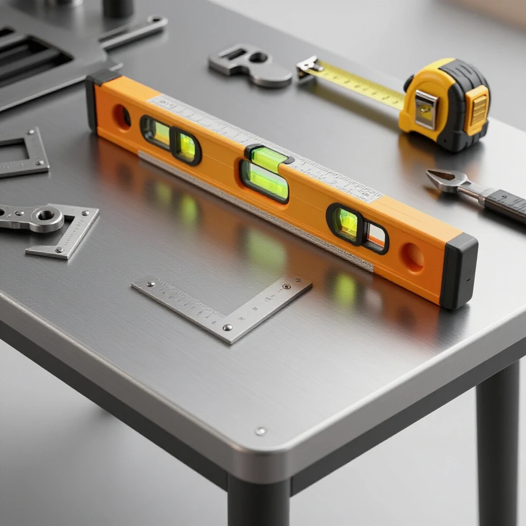
Manual layout tools are the primary instruments used to verify that a fabrication is square, flat, and parallel without the need for expensive electronics. These include machinist squares for 90-degree checks, straightedges for flatness, and feeler gauges to measure tiny gaps between components.
In a professional shop, we don’t rely on the same squares used for woodworking. A machinist square is a solid piece of hardened steel with no moving parts, manufactured to tolerances of 0.0005 inches or better. When you are aiming for a 0.5 mm tolerance in a garage fabrication safety environment, these are your best defense against “stacking errors.” A stacking error occurs when a small mistake in one corner is magnified as you move across the project.
- Machinist Squares: These provide a fixed 90-degree reference that won’t flex under the weight of steel.
- Straightedges: A precision-ground steel bar used to find high or low spots on your table.
- Dial Indicators: A tool that measures small distances (usually 0.001 inch) to check if a surface is parallel to your movement.
- Feeler Gauges: Thin strips of metal used to quantify the “daylight” you see under a square or straightedge.
- Shims: Small, flat pieces of metal used to lift a low corner until it meets the required plane.
| Tool Type | Primary Use | Expected Tolerance |
|---|---|---|
| Machinist Square | Verifying 90-degree corners | 0.01 mm per 100 mm |
| Steel Straightedge | Checking surface flatness | 0.05 mm over 1 meter |
| Dial Indicator | Measuring parallelism | 0.02 mm increments |
| Feeler Gauges | Measuring gap distance | 0.03 mm to 1.0 mm |
Leveling Your Build Surface with Shims and Straightedges
Leveling is the process of ensuring your work surface is a single, flat plane, free from twists or “wind.” Using a precision straightedge and metal shims, a fabricator can compensate for floor irregularities or table warping to create a reliable foundation for assembly.
Before you can square a fixture, your table must be flat. A common mistake I see is confusing “level” with “flat.” A table can be perfectly level according to a bubble, but still have a “dish” in the center. To check this, lay your straightedge across the table in an “X” pattern—from corner to corner. If you can slide a 0.1 mm feeler gauge under the center of the straightedge, your table is dished.
To correct this, we use shims. I prefer using stainless steel shim stock because it doesn’t compress or rust. If your table is a heavy plate on a frame, you can place shims between the table legs and the floor, or between the frame and the tabletop. Your goal is to eliminate any “rocking” or gaps. Once the table is flat within 0.5 mm, you have a “datum plane”—a reliable starting point where all other measurements are born.
Mastering 90-Degree Perpendicularity in Frame Setup
Perpendicularity is the state of two surfaces being exactly 90 degrees to one another, ensuring that vertical and horizontal members meet squarely. This is achieved by using the 3-4-5 triangulation method or high-grade machinist squares to eliminate angular errors that cause structural twisting.
When setting up a vertical fixture, I always use a “master square” technique. Place the square against your vertical member and look for light between the tool and the steel. If you see a sliver of light at the top, the member is leaning away. If you see light at the bottom, it’s leaning toward the tool.
- Clean the surface: Even a single metal shaving or a drop of oil can throw a square off by 0.2 mm.
- Clamp lightly: Over-tightening a clamp before the piece is square can “bow” the metal.
- Check both sides: Never assume that because one side is square, the other is too. Metal can have internal stresses that make it “diamond-shaped.”
- The 3-4-5 Rule: For large frames where a square isn’t big enough, measure 3 feet on one side, 4 feet on the other, and the diagonal must be exactly 5 feet. This is basic trigonometry used to verify structural metal load capacity paths.
Verifying Parallelism Using Dial Indicators
Parallelism ensures that two separate parts of a fixture remain the same distance apart along their entire length. By using a dial indicator mounted on a sliding base, a fabricator can detect if a rail or support is tapering inward or outward, which would cause the final assembly to bind or fail.
Parallelism is the silent killer of moving parts. If you are building a fixture for a sliding gate or a heavy drawer system, being “close” isn’t enough. I use a dial indicator to “sweep” the length of the part. Set the indicator to zero at one end and slide it to the other. If the needle moves, your part is crooked.
In my years of industrial structural verification, I’ve found that parallelism errors often stem from the material itself. Cold-rolled steel is generally flatter and more parallel than hot-rolled steel, which often has a “mill scale” or slight twist from the cooling process. If your dial indicator shows a deviation of more than 0.5 mm over a 300 mm span, you must use shims or adjust your clamping pressure to pull the part back into alignment.
Structural Joint Failure Analysis: The Cost of Misalignment
Structural joint failure analysis is the study of why a connection breaks, often revealing that poor initial alignment caused stress to concentrate in one small area. Misaligned fixtures lead to joints that are “pre-stressed,” meaning they are already fighting internal forces before they ever support an external load.
When a joint is not square, the weld has to fill a “gap” that varies in size. This leads to uneven cooling and internal tension. In the world of welding defect troubleshooting, we call this “fit-up error.” A poor fit-up is the leading cause of “root cracks,” which are cracks that start at the bottom of a joint where you can’t see them.
- Stress Concentration: A misaligned corner acts like a lever, multiplying the force on the weld.
- Brittle Fracture: If the metal is under constant tension from a poor setup, it is more likely to snap suddenly rather than bend.
- Reduced Load Capacity: A frame that is 5% out of square can lose up to 20% of its rated weight capacity.
| Alignment Error | Resulting Defect | Structural Impact |
|---|---|---|
| Out of Square (Angular) | Eccentric Loading | High risk of buckling under compression |
| Non-Parallel Rails | Binding/Friction | Accelerated wear and mechanical fatigue |
| Surface Un-flatness | Twisting (Wind) | Torsional stress on all connecting joints |
| Large Fit-up Gaps | Excessive Shrinkage | High internal residual stress |
Workshop Safety Protocols for Heavy Fixture Assembly
Workshop safety protocols are a set of mandatory procedures designed to prevent injury when handling heavy, sharp, or hot metal components. This includes using proper lifting techniques, securing workpieces to prevent tipping, and wearing appropriate Personal Protective Equipment (PPE) like Shade 10-13 filters for eye protection.
Handling large steel plates for fixtures is dangerous. A 4’x8′ sheet of 1/2-inch steel weighs over 650 pounds. If your table isn’t properly leveled and secured, that weight can shift, leading to a “near-miss” or a crushed limb. Always follow a workshop safety checklist before starting your layout.
- Clear the Floor: Trip hazards are magnified when you are carrying heavy steel.
- Check Clamp Integrity: Ensure your clamps are rated for the weight they are holding.
- Ventilation: Even during the layout phase, ensure your garage fabrication safety includes air movement to clear dust and metal filings.
- PPE Check: Wear cut-resistant gloves when handling raw steel edges and safety glasses even when just using a square.
Diagnostic Tests for Fixture Verification
Diagnostic tests are the final verification steps taken to confirm that a fixture is ready for use. These tests involve “dry fitting” components and performing a final sweep with measuring tools to ensure no movement occurred during the clamping process.
Once everything is clamped, I perform what I call the “Force Test.” I apply moderate manual pressure to the fixture to see if anything shifts. If it moves under my hand, it will definitely move when the heat of welding is applied. I also re-verify the 90-degree corners. It is a frustrating reality that clamping one corner often pulls another corner out of square.
- The Light Gap Test: Hold a flashlight behind your square. If light leaks through, the joint isn’t flush.
- The Diagonal Comparison: Measure the diagonals of a rectangular frame. They must be identical within 1 mm for the frame to be square.
- The Dial Sweep: One last pass with the dial indicator to ensure no “bowing” occurred during clamping.
Actionable Tracking Framework for Quality Control
A tracking framework is a simple checklist or log used to record measurements at each stage of the setup. This creates a data-driven history of the build, allowing the fabricator to identify exactly where an error occurred if the final project fails to align.
I recommend keeping a small notebook on your bench. Record your “Target Measurement” versus your “Actual Measurement.” This habit, common in industrial steel inspection, forces you to slow down and acknowledge deviations.
- Table Flatness Check: [ ] Pass/Fail (Tolerance: 0.5 mm)
- Primary Axis Squareness: [ ] Pass/Fail (Tolerance: 0.5 mm)
- Parallelism of Supports: [ ] Pass/Fail (Tolerance: 0.5 mm)
- Clamp Security Check: [ ] Pass/Fail
- Final Diagonal Verification: [ ] Measurement A: _ Measurement B: _
Conclusion
Precision in your initial setup is the foundation of structural safety. By using manual tools like machinist squares, straightedges, and dial indicators, you can ensure your project handles its intended load without the risk of catastrophic failure. Remember that metal is a dynamic material; it reacts to every force you apply. Treating the alignment phase with the same respect as the welding phase will save you time, material, and frustration. Your next step should be to clear your work surface and perform a “flatness sweep” with a straightedge. Once you know your table is true, every measurement you take afterward will be one you can trust.
FAQ
How do I know if my machinist square is actually square? You can perform a “flip test.” Place the square against a known straight edge and draw a line. Flip the square over and see if the edge still aligns with the line. If there is a gap that widens at the top or bottom, the tool is inaccurate and should be replaced.
What is the maximum allowable gap in a joint before it becomes a safety risk? For most structural projects, a gap larger than 1.5 mm (1/16 inch) is problematic. Large gaps require more weld metal, which increases heat input and leads to greater distortion and internal stress.
Why shouldn’t I use a standard tape measure for squaring small fixtures? Tape measures have a “floating hook” that can become bent or clogged with debris. For high-precision layout, a solid steel rule or a dial caliper is much more reliable because it removes the mechanical play found in tape hooks.
Can I use wood shims to level my welding table? No. Wood compresses under heavy weight and is a fire hazard in a metal shop. Always use steel, stainless steel, or brass shims for leveling your build surface to ensure a stable, non-flammable foundation.
What does “out of wind” mean in fabrication? “Wind” (pronounced like “find”) refers to a twist in a flat surface. If you have two parallel rails and one corner is higher than the others, the part is “in wind.” Getting it “out of wind” means making all four corners sit on the same flat plane.
How often should I check the alignment of my fixture during a build? You should check it before you start, after you apply clamps, and periodically throughout the process. Vibration and physical handling can cause clamps to slip or metal to shift.
Is a 0.5 mm tolerance really necessary for a hobbyist project? Yes, because errors are cumulative. A 0.5 mm error at the base of a 4-foot tall structure can result in a 5 mm or 10 mm error at the top. Staying tight on tolerances early prevents major headaches later.
What is the best way to clean mill scale off steel before squaring? Use a wire wheel or a flap disc on an angle grinder. Removing mill scale ensures your square sits directly on the metal, providing a more accurate reading than if it were resting on the flaky, uneven surface of the scale.
Does temperature affect my fixture alignment? Yes. Metal expands when warm. If you set up your fixture in a freezing garage and then move it to a heated shop, or vice versa, the dimensions can shift slightly. Try to perform your final alignment at a stable, room-temperature environment.
What is “eccentric loading” in simple terms? It is like trying to balance a heavy box on the very edge of a table instead of in the middle. The weight isn’t going straight down, so it creates a “tipping” or “twisting” force that the structure wasn’t designed to handle.
(This article was written by one of our staff writers, James Harlan. Visit our Meet the Team page to learn more about the author and their expertise.)