How to Stop Tool Chatter When Countersinking Steel (DIY Fix)
Few things in a workshop are as frustrating as the high-pitched screech of a tool vibrating against metal. I remember a project about ten years ago involving a series of 4mm mild steel plates. I was using a standard drill press, and every time I tried to create a seat for a flush-head screw, the machine would howl. Instead of a smooth, conical recess, I ended up with a ragged, multi-sided hole that looked more like a stop sign than a circle.
That experience taught me that surface defects are rarely the fault of the metal itself. Usually, they are symptoms of a breakdown in the relationship between the tool, the machine, and the workpiece. As a millwright, I’ve learned that solving these issues requires a systematic approach. You can’t just pull the lever harder and hope for the best. You have to isolate the variables, check your mechanical baselines, and understand the physics of what is happening at the cutting edge.
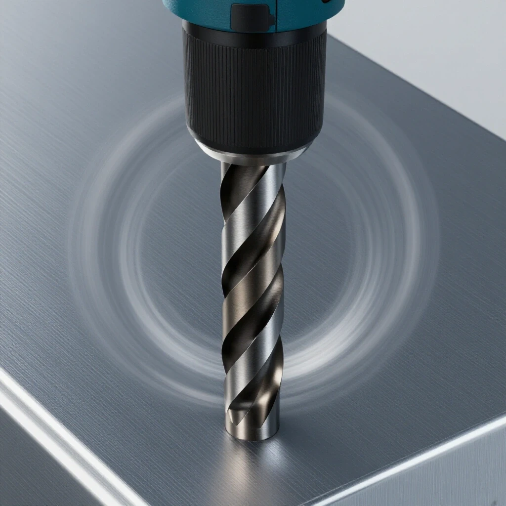
This guide focuses on diagnosing and resolving those rhythmic vibrations that ruin your finish when working with steel. We will look at how to stabilize your setup, adjust your manual inputs, and use simple shop materials to dampen the harmonics that lead to poor results.
The Physics of Harmonic Distortion in Metalworking
Harmonic distortion, often referred to as chatter, is a self-excited vibration that occurs when the cutting tool and the workpiece bounce off each other at a specific frequency. In manual operations, this usually happens because the system lacks the rigidity to resist the forces generated during the cut.
When you press a countersink bit into a steel plate, the tool wants to grab the material. If there is any “give” or flexibility in your drill press spindle or the workpiece itself, the tool will dig in, deflect, and then snap back. This cycle repeats hundreds of times per second. This creates the wavy, uneven pattern you see on the metal surface. In mild steel, which is relatively elastic compared to high-carbon alloys, this resonance can travel through the entire plate, turning it into a speaker diaphragm that amplifies the noise and the defect.
Understanding this cycle is the first step in a metalworking diagnostic guide. If you can break the rhythm of that vibration, you can stop the defect. We do this by increasing the stiffness of the setup or by introducing “damping” materials that soak up the energy before it can turn into a harmonic wave.
Identifying Mechanical Weak Points in Manual Drill Presses
Before you blame the bit or the steel, you must ensure your machinery is performing within its intended tolerances. Even a small amount of play in the machine can lead to significant tool chatter solutions being ineffective.
I always start by checking the spindle backlash. Backlash is the “slop” or movement within the mechanical parts of the machine. On a standard drill press, this often manifests as side-to-side movement in the quill. If you can grab the chuck and wiggle it more than 0.002 or 0.003 inches, you have a rigidity problem. This movement allows the tool to walk and vibrate as it enters the steel.
Spindle and Table Inspection Checklist
- Quill Tightness: Extend the quill halfway and try to move it laterally. If it moves, check for a tension adjustment screw on the side of the drill press casting.
- Chuck Seating: Ensure the Jacobs taper is clean and fully seated. A slightly tilted chuck will cause “runout,” where the tip of the bit moves in a small circle rather than spinning on a center point.
- Table Rigidity: Ensure the table is locked tight. On lighter hobbyist presses, the table can actually flex downward under the pressure of a countersink operation.
- Bit Sharpness: A dull tool requires more downward force, which increases the likelihood of the machine flexing and vibrating.
| Component | Tolerance/Metric | Impact on Finish |
|---|---|---|
| Spindle Runout | < 0.003 inches | High: Causes uneven cutting and “walking” |
| Quill Backlash | Minimal felt movement | Medium: Allows tool to deflect under load |
| Table Squareness | 90 degrees to spindle | Low: Affects hole geometry more than chatter |
| Spindle Speed | < 500 RPM | Critical: High speeds excite harmonics in steel |
Effective Dampening Techniques for Thin Steel Plate
When working with steel thinner than 6mm, the material itself acts like a tuning fork. Because it is thin, it lacks the mass to resist the energy of the cutting bit. This is where many mechanical troubleshooting steps focus on the workpiece rather than the tool.
One of the most effective DIY fixes I’ve used is the “wooden backer” method. By clamping your steel plate firmly to a piece of scrap hardwood or thick plywood, you change the resonant frequency of the workpiece. The wood absorbs the vibrations that would otherwise bounce back into the steel. It also prevents the “breakthrough” chatter that occurs when the bit starts to exit the bottom of the hole.
Improvised Damping Methods
- The Tape Wrap: Wrap a single layer of electrical tape or duct tape around the shank of the countersink bit. This provides a tiny amount of cushion that can break the harmonic link between the chuck and the tool.
- The Rubber Sandwich: Place a thin piece of rubber or a heavy gasket between the steel and the drill press table. This isolates the vibration and prevents the table from acting as a resonator.
- Mass Loading: For larger plates, clamping a heavy piece of bar stock near the area you are machining can add enough mass to move the resonant frequency out of the chatter range.
Building on this, the way you secure the work is vital. Use at least two clamps. If the plate can pivot or vibrate even slightly, you will never get a clean finish. I’ve seen many fabricators try to hold the work by hand; this is not only a safety risk but also a guaranteed way to induce tool chatter.
Speed and Feed Calibration for Manual Operations
In my 15 years of troubleshooting, I’ve found that the most common cause of surface defects in steel is simply running the tool too fast. Steel is a tough, gummy material that generates a lot of heat. When you run a countersink at high speeds, the cutting edges skip across the surface rather than biting into it.
For manual countersinking in mild steel, you should rarely exceed 500 RPM. In fact, for holes larger than 12mm, I often drop down to 200 or 300 RPM. The goal is to create a continuous chip. If you see fine dust or tiny needles, you are likely spinning too fast or not applying enough pressure.
Calculating Manual Feed Rates
In a professional shop, we talk about “Inches Per Tooth” (IPT). In a DIY setting, you have to feel this through the handle. You want a “heavy” feed. This means applying enough consistent downward pressure so the tool stays buried in the cut. If you let the tool “skate” on the surface, it will begin to vibrate immediately.
- Consistent Pressure: Once you start the cut, do not let up. A momentary lapse in pressure allows the tool to bounce, which starts the chatter cycle.
- Lubrication: Use a dedicated cutting fluid or even a drop of motor oil. This reduces friction and helps the tool slide through the material rather than grabbing and tearing.
- Chip Clearance: Periodically lift the tool to clear out the steel curls. If chips get trapped under the cutting edge, they will cause the tool to jump.
Tool Geometry and the Role of Flute Count
Not all countersink bits are created equal. If you are using a standard multi-flute bit (the ones with 5 or 6 cutting edges), you are more likely to experience vibration. This is because multiple teeth are hitting the material at the same time, which can easily sync up with the machine’s natural frequency.
For steel thinner than 6mm, I almost always recommend a single-flute countersink or a “zero-flute” (hole-through) style bit. These designs are far less likely to chatter because there is only one primary point of contact. This breaks the harmonic cycle before it can start.
Comparing Tool Designs
- Multi-Flute (3-6 flutes): Best for harder alloys or when used in high-rigidity industrial machines. In a DIY drill press, they often “chatter” because the teeth fight each other.
- Single-Flute: Excellent for manual operations. They require more downward pressure but produce a much smoother finish in mild steel.
- Zero-Flute (Cross-hole): These look like a solid cone with a hole drilled through them. They are the “gold standard” for preventing chatter in thin materials because they shear the metal rather than scraping it.
Interestingly, the angle of the bit matters too. Ensure your bit matches the fastener (usually 82 degrees for standard US screws or 90 degrees for metric). Using the wrong angle forces the tool to remove more material than necessary, increasing the load and the chance of vibration.
A Systematic Diagnostic Framework for Surface Defects
When a process that worked yesterday suddenly fails today, you need a framework to find the “electrical gremlins” or mechanical faults. I use a process of elimination. If I am getting chatter, I don’t change everything at once. I change one variable at a time.
First, I check the tool. Is it sharp? If yes, I move to the machine. Is everything locked down? If yes, I move to the technique. Am I going too fast? By following a fault-tree, you avoid the frustration of “random guesswork” and get back to productive work faster.
The Fault-Tree for Countersinking Issues
- Is the hole “chattered” (wavy)?
- Yes -> Reduce RPM by 50%.
- Still chattering -> Increase downward pressure (heavy feed).
- Still chattering -> Clamp a wooden backer to the steel.
- Still chattering -> Switch to a single-flute or zero-flute bit.
- Is the hole “torn” or “burred”?
- Yes -> Check tool sharpness.
- Yes -> Apply more cutting fluid.
- Is the hole off-center?
- Yes -> Check for spindle runout or workpiece movement.
Case Study: The Singing 5mm Plate
I once consulted for a shop that was struggling with a series of 5mm steel brackets. They were using a heavy-duty drill press, but every countersink was coming out hexagonal. They had tried different speeds and even bought new bits, but the problem persisted.
Upon inspection, I noticed they were using a “floating” vice that wasn’t bolted to the drill press table. Even though the vice was heavy, the 5mm plate was thin enough that it was vibrating within the vice jaws. We did three things to fix it: 1. We bolted the vice to the table. 2. We placed a scrap piece of 12mm plywood inside the vice, directly under the steel plate. 3. We switched from a 5-flute bit to a zero-flute bit.
The result was a silent, mirror-smooth finish. The “fix” wasn’t a new machine; it was simply managing the harmonics of the setup. This is a classic example of how mechanical troubleshooting steps can resolve seemingly complex metal fabrication fixes.
Actionable Tracking and Maintenance History
To avoid these issues in the future, I recommend keeping a small logbook near your primary machines. This helps you track what works for specific materials. If you know that a certain RPM and bit type worked perfectly for 4mm steel six months ago, you don’t have to reinvent the wheel today.
Tool Calibration Checklist
- Weekly: Wipe down the drill press column and lubricate the rack and pinion.
- Monthly: Check the belt tension. A slipping belt can cause intermittent speed changes that induce chatter.
- Monthly: Use a dial indicator to check spindle runout. If it exceeds 0.005 inches, it may be time to replace the bearings.
- Per Project: Verify that the table is perpendicular to the spindle using a machinist’s square.
By maintaining your equipment and following a structured approach, you can eliminate the downtime associated with “hard-to-find” issues like resonant vibrations.
Conclusion and Next Steps
Dealing with tool vibration is a rite of passage for many fabricators. It tests your patience and your ability to look past the surface of a problem. Remember that the “screech” is just energy looking for a way out. If you provide a rigid path for that energy or a way to dampen it, the noise and the defects will disappear.
Start by slowing down. Most DIY errors come from excessive speed. From there, focus on rigidity—clamp your work, use a backer, and ensure your machine is tight. If you still face issues, look at your tool geometry. A single-flute bit is often the “magic bullet” for manual steel work.
As you develop these systematic diagnostic skills, you’ll find that you spend less time fighting your tools and more time finishing high-quality projects. Keep your tools sharp, your belts tight, and your feed rates heavy.
FAQ: Troubleshooting Manual Metalworking Vibration
Why does my drill press vibrate only when I start the countersink?
This is usually due to “entry shock.” The multi-flute bit is trying to grab the metal, but because there is no pilot hole for the center of the countersink, it walks. Try using a bit with a pilot guide or ensure you are using a very slow RPM and high pressure to “seat” the tool quickly.
Can I use a standard twist drill to make a countersink?
While possible, it is not recommended. A standard drill bit has a 118-degree or 135-degree point, which does not match the 82-degree or 90-degree angle of flush fasteners. This results in poor contact and a weak mechanical joint.
How do I know if my spindle bearings are bad?
If you hear a grinding noise or feel heat coming from the spindle housing after a few minutes of use, the bearings are likely worn. Another test is to check for lateral play (backlash) using a dial indicator. Any movement over 0.005 inches is a sign of trouble.
Does the type of steel matter for chatter?
Yes. Mild steel (like A36) is more prone to chatter than harder steels because it is more ductile. It “gives” more under the tool, which can lead to the bouncing effect. Harder steels tend to resist this but require even slower speeds and better lubrication.
What is the best lubricant for manual steel drilling?
For DIY projects, a dedicated sulfur-based cutting oil is best. If that isn’t available, a 3-in-1 oil or even clean motor oil will help. Avoid WD-40 for actual cutting; it is a better cleaner/penetrant than a high-pressure lubricant.
Why is my hole coming out shaped like a triangle?
This is a classic sign of “three-lobe chatter.” It happens when the tool’s vibration frequency synchronizes with its rotation. Switching to a tool with an odd number of flutes (like a single-flute bit) or significantly changing your RPM will usually break this pattern.
Should I pilot drill before countersinking?
Yes, you should always have the through-hole drilled before you attempt to countersink. The through-hole should match the diameter of the screw shank. The countersink bit then follows this hole, which helps center the tool and reduces the amount of material it has to remove.
Is it safer to countersink by hand or on a press?
A drill press is always safer and more consistent. Handheld drilling makes it nearly impossible to maintain the perpendicularity and constant pressure required to prevent vibration. If you must use a handheld drill, use a very low speed and a zero-flute bit.
How can I tell if my feed rate is correct?
Look at the chips. You want long, curly “swarf.” If the chips are blue, you are generating too much heat (too much speed, not enough feed). If the chips are tiny crumbles, you aren’t pushing hard enough.
What is “Back-EMF” and does it affect my drill press?
Back-EMF is an electrical phenomenon in motors, but in the context of manual drill presses, it is rarely a factor unless you have a sophisticated motor controller. For most DIYers, focus on the mechanical aspects like belt tension and pulley alignment instead of electrical faults.
Can I use tape to stop chatter on any tool?
Yes, a small wrap of tape on the shank can help, but never put tape on the cutting edges. The goal is to create a dampening interface between the tool and the chuck.
What is the most important rule for stopping chatter?
The most important rule is: Increase rigidity and decrease speed. If you do those two things, 90% of your vibration issues in steel will vanish.
(This article was written by one of our staff writers, Paul Whitaker. Visit our Meet the Team page to learn more about the author and their expertise.)