Sound Dampening Pads for Air Compressors Compared (Review)
The workshop was quiet, except for the rhythmic ticking of a cooling weldment, until the 80-gallon compressor kicked on. Within seconds, the floor began to hum, and I watched a bead of sweat on my welding helmet vibrate. More importantly, the TIG arc I was trying to steady began to dance. This wasn’t a problem with my hand or the machine settings; it was a mechanical resonance issue. After 18 years in industrial fabrication, I’ve learned that the most elusive problems, like tool chatter or weld porosity, often stem from environmental factors we overlook.
Vibration is a silent killer of precision. It travels through concrete slabs, travels up machine legs, and manifests as tiny inconsistencies in a lathe’s finish or a sudden shift in a mill’s alignment. When a compressor cycles, it generates kinetic energy that has to go somewhere. If it goes into the floor, it’s affecting every other tool in the shop. My approach to resolving this involves systematic isolation using various damping materials to break that energy path.
In this guide, we will break down the diagnostic process for identifying vibration-related faults and compare the materials used to isolate heavy pneumatic equipment. We aren’t looking for a “quick fix” that wears out in six months. We are looking for a permanent mechanical solution based on material density, thickness, and proper installation techniques.
Establishing a Diagnostic Framework for Workshop Vibrations
A diagnostic framework is a structured method used to identify the root cause of mechanical interference by isolating variables one at a time. It prevents the technician from making random adjustments and ensures that every change is backed by measurable data.
When I walk into a shop where a fabricator is complaining about tool chatter or “ghost” errors in their CNC, the first thing I do is look at the floor. Vibration is essentially energy moving through a medium. To solve it, we have to map the path of that energy. Is it coming from the machine itself, or is it being “imported” from a nearby compressor?
I use a three-step process: Observation, Isolation, and Verification. First, I observe the defect—perhaps a wavy finish on a turned part. Second, I isolate the variables. I’ll run the lathe with the compressor off, then with it on. If the chatter only appears when the compressor is charging, I’ve found my source. Verification involves measuring the frequency of that vibration to choose the right damping material.
Mapping the Energy Path from Source to Tool
Energy path mapping is the process of tracing how mechanical movement travels from a vibrating source through the shop’s structure to a precision instrument. This allows a fabricator to see where the “bridge” is located and where to place isolation materials.
Think of your shop floor as a giant drumhead. When the compressor runs, it’s like a drumstick hitting that head. The energy ripples outward. If your lathe or welding table is sitting on the same slab, those ripples travel up the legs. This can cause “micro-shaking” in your torch hand or the tool post.
To map this, I often use a simple vibration app on a smartphone or a dedicated digital accelerometer. I place the sensor on the compressor tank, then on the floor six inches away, then at the base of the affected tool. If the readings are nearly identical, the floor is acting as a perfect conductor. Our goal is to break that conductivity using materials that absorb and dissipate that energy as low-level heat.
Material Properties for Effective Vibration Isolation
Material properties refer to the physical characteristics of a substance, such as its density, Shore hardness, and elasticity, which determine how it reacts to stress. In vibration damping, these properties dictate whether a pad will compress too much or stay too rigid to be effective.
Not all rubber is created equal. I’ve seen guys use old carpet scraps or pieces of plywood under their compressors. These are useless. To truly isolate a heavy machine, you need to understand Shore Hardness (Durometer). This is a measure of how resistant a material is to permanent indentation. For a standard shop compressor, we usually look for a Shore A rating between 40 and 60.
If the material is too hard (high durometer), the vibration passes right through it. If it’s too soft (low durometer), the weight of the compressor will crush it flat, “bottoming out” the pad and re-establishing a solid connection to the floor. We are looking for the “Goldilocks” zone where the material stays resilient under the static load of the tank.
Comparing Common Damping Media
Damping media comparison involves evaluating different materials like ribbed rubber, cork-and-rubber composites, and high-density polymers to see which provides the best energy absorption. Each material has a specific frequency range where it performs best under heavy pneumatic loads.
In my repair logs, I’ve tracked the performance of four main types of isolation materials. Here is how they stack up based on my field testing:
| Material Type | Best For | Typical Thickness | Shore Hardness |
|---|---|---|---|
| Ribbed Rubber Pads | General use, oily environments | 3/8″ to 1/2″ | 50-60 Shore A |
| Cork & Rubber Composite | High-frequency vibration, light loads | 7/8″ | 40-50 Shore A |
| High-Density Sorbothane | Precision isolation, heavy dampening | 1/2″ to 1″ | 30-50 Shore A |
| Waffle-Pattern Neoprene | Multi-directional movement | 5/16″ | 60 Shore A |
Building on this, ribbed rubber is the workhorse of the shop. The ribs provide “gap space” for the material to expand into when compressed, which helps with energy dissipation. Cork-and-rubber pads are excellent because the cork provides a different resonant frequency than the rubber, effectively “confusing” the vibration waves and stopping them more efficiently.
The Role of Thickness and Surface Area
Thickness and surface area determine how much weight a damping pad can support while still maintaining its ability to flex. If a pad is too thin, it cannot deform enough to soak up the vertical movement of a reciprocating pump.
I generally recommend a minimum thickness of 1/2 inch for any compressor over 30 gallons. As the thickness increases, the pad’s ability to handle lower-frequency vibrations improves. However, you have to be careful with surface area. If you use a pad that is too large, the weight of the compressor is spread too thin, and the pad won’t compress enough to become “active.”
The goal is to have the pad compressed by about 10% to 15% of its original height under the static weight of the machine. This puts the material in its optimal operating range. If you have a 500-pound compressor on four feet, each foot carries 125 pounds. You should size your pads so that this 125-pound load achieves that 10% compression.
Systematic Installation and Mounting Strategies
Installation and mounting strategies are the technical procedures used to secure machinery while maintaining a physical break between the machine and the floor. Proper mounting ensures that bolts do not create a “bridge” that bypasses the isolation pads.
The biggest mistake I see in fabrication shops is “short-circuiting” the isolation. A fabricator puts a nice rubber pad under the compressor foot, then runs a heavy steel bolt through the foot, through the pad, and into the concrete. That bolt is now a high-speed highway for vibration. You’ve essentially done nothing.
To fix this, you need to use isolation washers. A proper mount looks like a sandwich: the floor, the damping pad, the compressor foot, a rubber washer, a steel fender washer, and then the nut. This ensures that no metal part of the compressor is in direct contact with the mounting bolt or the floor.
Step-by-Step Isolation Mounting
- Clean the Base: Ensure the concrete under the compressor is level and free of oil. Oil can degrade certain types of rubber over time.
- Level the Unit: Use a precision level on the tank’s mounting brackets. An unlevel compressor puts uneven stress on the pads, leading to premature failure.
- Select the Pad: Based on the weight of the unit, choose a pad that will compress 10-15%.
- Install Isolation Bushings: If bolting to the floor, ensure the bolt hole in the compressor foot is large enough to accommodate a rubber sleeve or bushing.
- Torque Carefully: Do not over-tighten the mounting bolts. You want them “snug” enough to prevent the machine from walking, but loose enough that the rubber isn’t squashed into a solid mass.
Interestingly, some of the best results I’ve had were with “floating” installations. If the compressor is heavy enough and doesn’t “walk” during startup, simply letting it sit on high-friction rubber pads without bolts can provide the best vibration isolation possible.
Measuring the Impact of Isolation Materials
Measuring impact involves using quantitative tools to record noise and vibration levels before and after an intervention. This data confirms whether the chosen solution has successfully reduced the interference to acceptable shop tolerances.
In the world of diagnostics, if you didn’t measure it, it didn’t happen. I use a decibel (dB) meter to track noise reduction, but more importantly, I use a vibration spectrum analyzer (often a smartphone app like ‘Physics Toolbox’) to see the frequency drop.
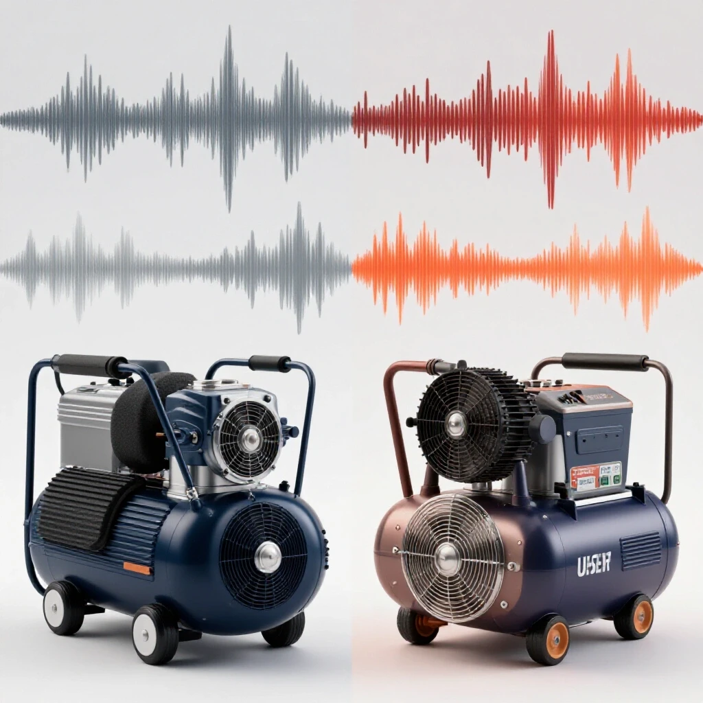
When a compressor is bolted directly to the floor, you might see a peak at 60 Hz (the motor speed) and another at the reciprocating frequency of the pump. After installing proper pads, those peaks should drop significantly in amplitude. We aren’t just looking for it to be “quieter”; we are looking for the floor’s movement to drop below the threshold that affects our other tools.
Expected Decibel and Vibration Reductions
| Metric | Unprotected | With Ribbed Rubber | With Composite Pads |
|---|---|---|---|
| Noise Level (at 3ft) | 88 dB | 84 dB | 82 dB |
| Floor Vibration (G-force) | 0.15G | 0.04G | 0.02G |
| Tool Chatter Incidence | High | Low | Negligible |
As a result of these measurements, we can see that while the decibel drop might seem small (4-6 dB), the reduction in floor vibration is massive—often over 70%. That is the difference between a lathe finish that looks like a mirror and one that looks like a record sleeve.
Case Study: The Shaking Welding Table
I once consulted for a shop that was struggling with consistent porosity in their stainless steel TIG welds. They had checked their gas coverage, replaced their liners, and even swapped out their shielding gas tanks. Nothing worked. The porosity was intermittent and seemed to happen more in the afternoons.
I sat and watched the welder for an hour. I noticed that every time the shop’s large reciprocating compressor kicked on in the corner, the welder’s hand seemed to tensed up. I placed a glass of water on the welding table. When the compressor ran, the water showed clear concentric rings—vibration.
This vibration was so subtle it wasn’t shaking the torch out of his hand, but it was causing the gas lens to oscillate just enough to pull in atmospheric air. We installed 1-inch thick composite cork-and-rubber pads under the compressor and used isolation bushings on the mounting bolts. The vibration at the welding table dropped by 85%, and the porosity issues vanished immediately. This is why systematic diagnostics are better than guesswork.
Troubleshooting Common Installation Failures
Troubleshooting installation failures is the process of identifying why a damping solution isn’t working as expected. This usually involves looking for mechanical bridges, material degradation, or improper loading.
If you’ve installed pads and the shop is still shaking, the first thing to check is “bridging.” Is there a hard-pipe air line connected directly from the compressor to the wall? If so, that pipe is acting like a tuning fork, carrying the vibration past your pads and into the building’s framing. You must use a flexible braided hose (a “vibration loop”) between the compressor and your main shop piping.
Another common failure is “pad hardening.” Over years of exposure to shop heat and oil, some cheap rubber pads will turn as hard as plastic. When this happens, they lose all damping capability. I recommend inspecting pads every 12 months. If you can’t indent the rubber with a fingernail, it’s time to replace them.
Checklist for a Successful Isolation Setup
- Flexible Connections: Ensure all air lines and electrical conduits have a flexible loop.
- No Metal-to-Metal: Verify that mounting bolts are isolated with rubber bushings.
- Uniform Loading: Check that all four (or three) feet are carrying an equal load.
- Environment Check: Ensure the pads are rated for oil and grease exposure.
- Clearance: Make sure the compressor tank isn’t touching any walls or workbenches.
Tool and Calibration Checklist for Diagnostics
To perform these diagnostics accurately, you need a specific set of tools. These aren’t expensive, but they provide the data needed to move beyond “feeling” the problem.
- Digital Decibel Meter: To measure the ambient noise reduction.
- Vibration Analyzer App: To map the frequency and intensity of floor movement.
- Shore A Durometer Tester: To verify the hardness of your damping materials.
- Precision Level: To ensure the compressor isn’t leaning, which causes uneven wear.
- Infrared Thermometer: To check if the pads are overheating (a sign of excessive energy absorption or friction).
By keeping a log of these readings, you can track the performance of your isolation strategy over time. If the vibration levels start to creep back up, you’ll know it’s a material failure rather than a machine fault.
Practical Next Steps for the Fabricator
If you are facing tool chatter or weld defects that seem to coincide with your compressor’s cycle, don’t start tearing your tools apart. Start with the floor. Buy a small set of varied isolation pads and experiment with the water-glass test. It’s a low-cost way to see immediate improvements in your shop’s precision.
Remember, the goal is to break the energy path. Every piece of equipment in your shop should be its own “island,” mechanically isolated from the others. Once you master this, you’ll find that your tools stay in alignment longer, your welds are cleaner, and your shop is a much more focused environment to work in.
FAQ: Frequently Asked Questions
How do I know if my vibration pads are bottoming out? You can tell a pad is bottomed out if it looks completely flat or if you can no longer see the ribs or “waffle” pattern in the material. A functional pad should still have some visible “give” or springiness. If you place a pry bar under the compressor foot and lift slightly, the pad should bounce back. If it stays compressed, it has lost its elasticity and is no longer isolating the machine.
Can I stack multiple pads to get better results? Stacking pads can be effective, but it can also make the compressor unstable. If you stack pads, you increase the “stack height,” which can cause the compressor to rock or tip during startup torque. If you need more damping, it is usually better to move to a thicker, single-piece pad or a higher-quality material like Sorbothane rather than stacking multiple thin rubber sheets.
Does the floor material affect which pad I should choose? Yes. On a thick, reinforced concrete slab, high-frequency vibrations are the main concern, so cork-and-rubber composites work well. On a thinner slab or a wooden floor (common in some smaller shops), low-frequency “thumping” is the bigger issue. In those cases, you need thicker, softer pads with a lower Shore A rating to absorb the larger movements of the floor.
Why did my noise levels stay the same after installing pads? Damping pads are designed primarily to stop “structure-borne” noise (vibration traveling through the floor). They do very little for “airborne” noise (the sound of the intake and the pump). If your shop is still loud, the pads are likely doing their job of protecting your tools from vibration, but you may need an intake silencer or an enclosure to address the sound traveling through the air.
Are there materials I should avoid using as isolation pads? Avoid using wood, compressed cardboard, or standard “soft” foam like you’d find in a mattress. Wood and cardboard are too rigid and will eventually crack or compress into a solid. Soft foam will bottom out instantly under the weight of a compressor. Also, avoid natural rubber if your shop has a lot of oil or chemical overspray, as it will swell and degrade quickly. Use Neoprene or Nitrile-based pads instead.
How often should I replace my compressor’s isolation pads? In a standard fabrication environment, high-quality pads should last 3 to 5 years. However, you should inspect them annually for signs of “compression set” (where they don’t spring back) or “cracking” (ozone or heat damage). If your machine starts “walking” across the floor or if you notice a return of tool chatter, replace the pads immediately.
Is it better to bolt the compressor down or let it sit free? If the compressor is top-heavy or has a high center of gravity (like a vertical 80-gallon tank), it should be bolted for safety. However, use isolation bushings to ensure the bolts don’t transmit vibration. If it’s a low-profile, horizontal unit that stays put on its own, leaving it unbolted on high-friction pads often provides the best vibration isolation because there are zero mechanical “bridges” to the floor.
What is Shore Hardness, and why does it matter for my compressor? Shore Hardness is a standardized scale for measuring the flexibility of rubbers and plastics. For air compressors, the Shore A scale is used. A rating of 40A is soft (like a pencil eraser), while 70A is hard (like a car tire). If you choose a pad that is too hard for your compressor’s weight, it won’t compress enough to absorb vibration. If it’s too soft, the weight will crush it. Matching the hardness to the load is the key to effective diagnostics.
Can vibration pads help with my plasma cutter’s arc stability? Yes, indirectly. If your plasma cutter is on a CNC table, vibration from a compressor can cause the torch head to shake. This “micro-wobble” can lead to a jagged cut or inconsistent arc gap. Isolating the compressor stops this movement from reaching the CNC rails, resulting in a much smoother cut and better consumable life.
Do I need different pads for a rotary screw vs. a reciprocating compressor? Yes. Rotary screw compressors produce high-frequency, consistent vibration, which is easier to dampen with thinner, denser rubber or neoprene. Reciprocating (piston) compressors produce low-frequency, high-amplitude “thumps.” These require thicker pads with more “travel” or displacement capability, such as 7/8-inch cork-and-rubber or thick Sorbothane.
(This article was written by one of our staff writers, Paul Whitaker. Visit our Meet the Team page to learn more about the author and their expertise.)