How to Square Up Custom Welded Assemblies Safely (DIY Plan)
When I first started building metal furniture in my garage twelve years ago, I thought a tape measure was the only tool I needed to ensure a project was straight. I spent a full Saturday welding a heavy-duty shop stool, only to find it wobbled by nearly half an inch once I set it on the concrete floor. It wasn’t the floor that was crooked; it was my lack of a systematic approach to geometry. I had ignored the way heat pulls metal and the necessity of a flat reference plane. This experience taught me that precision isn’t about expensive machinery; it is about mastering the physical mechanics of layout and the sequence of manual adjustments.
Learning metal fabrication is a journey of developing your “eye” and your muscle memory. You have to learn how to feel when a clamp is tight enough and how to see a gap that is only a few thousandths of an inch wide. For those of you who are currently spending your weekends practicing joints and measuring your progress, understanding how to keep your work true is the bridge between a “hobbyist project” and a professional-grade assembly. We are going to break down the physical habits and manual checks that ensure your frames and structures are exactly where they need to be.
Establishing a True Reference Surface for Layout
A flat, stable work area is the foundation of all accurate metalwork. Without a known “zero” plane, every measurement you take will carry the cumulative errors of the surface beneath it. You cannot build a square frame on a bowed wooden bench or a cracked garage floor.
When I was a beginner, I tried to build a gate on a pair of uneven sawhorses. Every time I moved a clamp, the whole assembly shifted. I eventually learned that professional fabricators rely on a dedicated layout table. This doesn’t have to be a multi-thousand-dollar fixture table. A thick piece of steel plate or even a carefully leveled heavy-duty workbench can serve as your primary reference. The goal is to have a surface where you can trust that “flat” really means flat.
Why Surface Flatness Dictates Your Success
If your work surface has a “twist” or a “dip,” your assembly will follow that shape as you clamp it down. Even a 1/16-inch deviation over four feet can result in a frame that looks crooked once it is stood up. By using a long machinist’s straightedge, you can identify high and low spots on your table.
Before you begin any project, you should clear your reference surface of any old weld spatter or debris. Use a coarse sanding block or a scraper to ensure the metal sits flush. This simple habit of cleaning the “clean zone” prevents small particles from throwing off your vertical alignment by several degrees.
Essential Manual Tools for Geometric Precision
Basic hand tools like machinist squares and straightedges are the primary sensors for a fabricator. They provide immediate feedback on whether a joint is truly perpendicular or if a rail is bowing. Mastering these tools is about more than just owning them; it is about how you hold them and where you place your eyes.
I spent years refining my grip on a combination square. If you press too hard on one side, you can tilt the tool and get a false reading. You want a light, consistent touch. When checking a 90-degree corner, I always look for light passing through the gap between the tool and the metal. If I see a sliver of light at the top but not the bottom, I know exactly which direction the metal needs to move.
Selecting the Right Square for the Task
Not all squares are created equal. A standard carpenter’s square is great for rough layout, but for precision metalwork, you need a machinist square or a heavy-duty steel square that won’t flex under clamping pressure.
| Tool Type | Best Use Case | Accuracy Level |
|---|---|---|
| Machinist Square | Checking small internal joints | High (within .005″) |
| Framing Square | Large frame layout and 3-4-5 checks | Moderate |
| Combination Square | Marking cut lines and depth gauging | Moderate/High |
| Speed Square | Quick 45 and 90-degree checks | Low/Moderate |
The Role of Adjustable Clamps in Alignment
Clamps are your “extra hands,” but they can also be your worst enemy if used incorrectly. A common mistake is over-tightening a clamp on one side of a joint, which can “crush” the alignment or cause the metal to pivot away from your square. I recommend using F-style clamps or C-clamps with swivel pads. The swivel pad allows the clamp to apply pressure evenly without “walking” the metal across the table as you tighten the screw.
The Mechanics of the Tack-and-Check Cycle
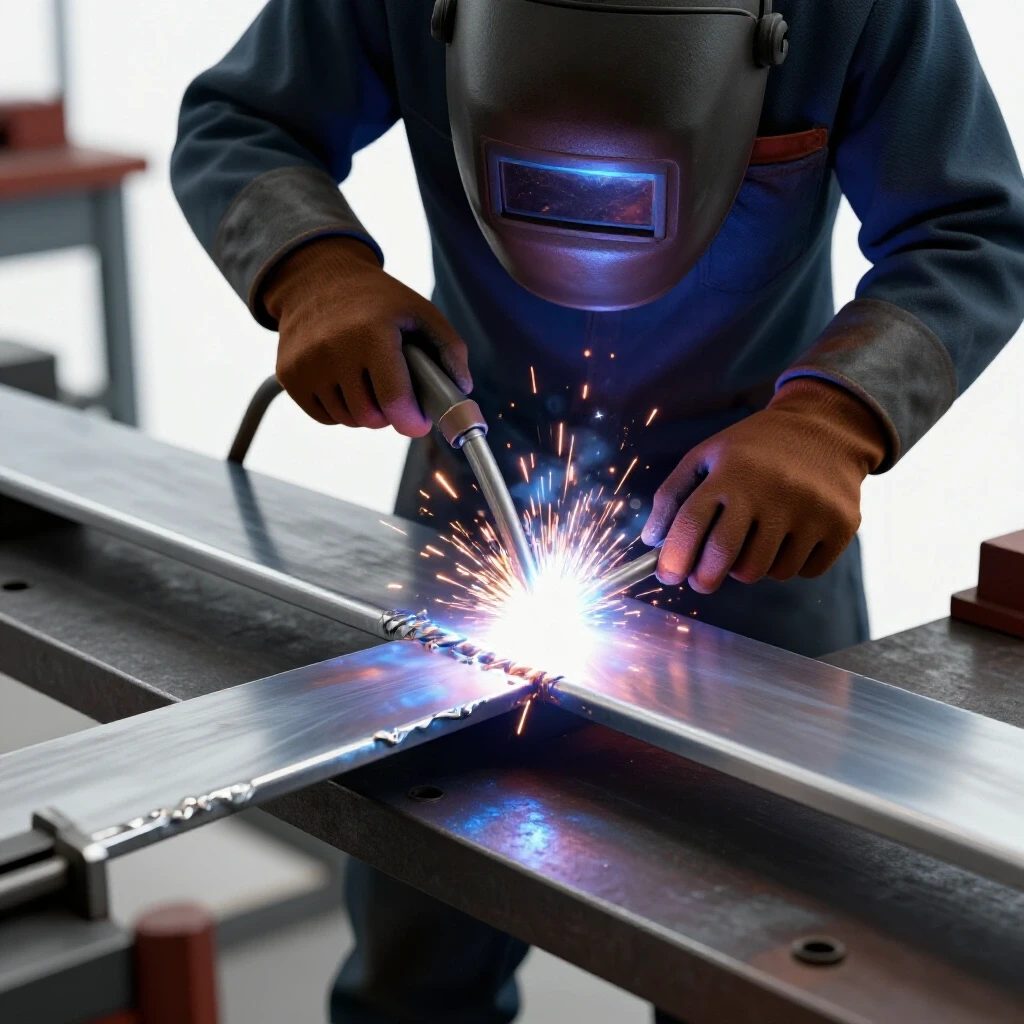
Small, strategic welds called tacks hold pieces in place for verification. This phase is the last chance to make manual adjustments before the heat of a full weld locks the geometry in. A tack weld acts like a temporary hinge; it is strong enough to hold the weight of the metal but small enough to be broken or bent if the alignment is off.
When I teach students, I emphasize the “four-point tack” method for tubing. You place one small tack on each side of the joint. However, before you do the second tack, you must re-check your squareness. Metal shrinks as it cools. That first tiny dot of molten metal will pull the joint toward itself as it solidifies. If you don’t account for this “draw,” your project will be out of square before you even finish tacking.
How to Sequence Your Tacks for Stability
The sequence in which you apply tacks determines how much the metal moves. If you tack all the corners on the outside first, the frame will likely “bow” inward. Instead, I follow a diagonal pattern, similar to how you tighten lug nuts on a car wheel.
- Place a single tack at the first corner and check for square.
- Move to the diagonally opposite corner, pull it into square, and tack.
- Check the “X” measurements (diagonal distances) of the frame.
- Apply tacks to the remaining two corners only after the diagonals match.
Correcting Misalignment with Manual Force and Shims
Metal is surprisingly flexible before it is fully joined. Using light hammer taps or thin metal shims allows a builder to nudge an assembly into the correct position. This is where the “feel” of fabrication comes into play. You aren’t trying to beat the metal into submission; you are using controlled kinetic energy to shift it.
I prefer using a dead-blow hammer or a heavy brass mallet for adjustments. A standard steel claw hammer can mar the surface of your work, creating more cleanup later. A dead-blow hammer delivers a “thud” that moves the metal without causing it to bounce back, which is essential when you are trying to close a 1/32-inch gap.
Using Shims to Level Uneven Components
Sometimes, the metal itself isn’t perfectly straight. Rectangular tubing often has a slight “crown” or “twist” from the factory. In these cases, a machinist square might show the joint is square, but the rest of the bar is leaning. This is where shims come in.
A shim is a thin piece of material—often a scrap of 16-gauge sheet metal or a dedicated steel feeler—placed under a low point to bring it up to the reference plane. By shimming the “low” side of a tube before clamping it down, you ensure that the entire assembly remains on the same horizontal plane. This prevents the “rocking chair” effect on finished tables or frames.
Sequential Plane Verification in Three Dimensions
A common plateau for intermediate fabricators is getting the frame square on the table but failing to realize it is “twisted” in the vertical plane. We call these the X, Y, and Z axes. Squaring up a custom assembly requires you to check all three planes in a specific order.
In my own shop, I follow a “bottom-up” verification process. First, I ensure the base is flat against the table (X and Y). Then, I use a level or a square to ensure the uprights are perfectly perpendicular to the base (Z). If you skip the vertical check, you might end up with a frame that looks like a rectangle from the top but looks like a leaning tower from the side.
The 3-4-5 Rule for Large Scale Accuracy
When an assembly is too large for a standard square, I rely on the Pythagorean theorem, specifically the 3-4-5 rule. If you measure 3 feet along one side and 4 feet along the adjacent side, the diagonal distance between those two points must be exactly 5 feet for the corner to be 90 degrees.
- Step 1: Mark a point exactly 3 inches (or feet) from the corner on one rail.
- Step 2: Mark a point exactly 4 inches (or feet) from the corner on the joining rail.
- Step 3: Adjust the rails until the distance between the two marks is exactly 5 inches (or feet).
- Step 4: Secure with a heavy clamp and apply your first tack.
Managing Heat Distortion Through Manual Restraint
One of the biggest frustrations in metalworking is watching a perfectly square assembly pull out of alignment during final welding. As metal heats up, it expands; as it cools, it contracts. This contraction is powerful enough to bend thick steel plate. Understanding this “pull” is key to maintaining the integrity of your layout.
I treat every weld as a tug-of-war. If I weld the inside of a corner, the cooling metal will “pull” the corner closed, making it less than 90 degrees. To counter this, I often “pre-set” my joints. I might tack a corner so it is slightly “open” (perhaps 91 degrees), knowing that the final weld will pull it back to a perfect 90. This takes practice and a lot of logging in your shop notebook to see how different thicknesses of metal react.
Strategies to Minimize “The Pull”
- Back-stepping: Instead of one long continuous bead, work in short segments, moving in the opposite direction of the overall weld.
- Staggering: Move from one side of the project to the other to allow heat to dissipate evenly.
- Clamping to the Table: Leave your clamps on until the metal is cool to the touch. The clamps act as a physical restraint against the shrinking forces.
Actionable Tracking for Skill Progression
To move past technical plateaus, you must measure your progress objectively. I recommend keeping a “Fabrication Log” where you record the results of every major assembly you square up. This helps you identify patterns in your errors—for example, if you notice your frames always pull to the left, you can adjust your clamping technique.
Sample Practice Log Template
| Project Date | Material Type | Target Dimension | Actual Dimension | Error Margin | Correction Method Used |
|---|---|---|---|---|---|
| Oct 12 | 2″ Sq Tube | 24.00″ Square | 24.125″ | +1/8″ | Hammered corner, re-tacked |
| Oct 15 | 1″ Angle Iron | 12.00″ Square | 12.00″ | 0.0″ | Used 3-4-5 rule, heavy clamping |
| Oct 20 | 3″ Flat Bar | 90 Deg Corner | 88 Deg | -2 Deg | Noted inside weld pull; need pre-set |
Skill Verification Checklist
Before you strike your first arc for final welding, run through this mental and physical checklist to ensure your assembly is truly ready.
- Table Check: Is the reference surface clear of spatter and debris?
- Diagonal Check: Are the corner-to-corner measurements within 1/16th of an inch?
- Light Gap Test: Can you see light between your square and the metal?
- Vertical Plumb: Are the uprights square to the table surface, not just the base?
- Tack Integrity: Are the tacks large enough to hold but small enough to allow for a “nudge” if needed?
- Clamp Pressure: Are the clamps firm but not distorting the metal’s natural shape?
Conclusion
Mastering the art of keeping an assembly true is a physical discipline that requires patience and a systematic approach. It is not about having the most expensive tools; it is about how you use your squares, how you listen to the “thud” of your hammer, and how you respect the way heat moves metal. By following a consistent layout routine—cleaning your reference surface, using the tack-and-check cycle, and managing distortion through strategic clamping—you will find that your projects begin to take on a professional level of precision.
Don’t be discouraged by the learning curve. Every fabricator, including myself, has built projects that ended up crooked. The difference between a beginner and an expert is the expert’s willingness to stop, measure, and correct the error before it’s too late. Your next step is to get into the shop, find a truly flat surface, and practice the 3-4-5 rule until it becomes second nature.
Frequently Asked Questions
Why does my frame always pull out of square after I finish welding?
This is caused by thermal contraction. As the molten weld pool cools, it shrinks and pulls the surrounding metal with it. To prevent this, keep your project clamped to a flat table until it is completely cool, and try “back-stepping” your welds to distribute the heat more evenly.
How do I know if my workbench is flat enough for layout?
You can check your table using a long, high-quality straightedge. Lay the edge across the table in multiple directions (horizontal, vertical, and diagonal). If you can slide a piece of paper under the straightedge at any point, your table has a low spot that could affect your accuracy.
What is the most accurate way to check a square corner?
The most reliable method is measuring the diagonals of a rectangular frame. If the distance from the top-left corner to the bottom-right corner is exactly the same as the top-right to the bottom-left, the frame is square. This is more accurate than using a small square because it accounts for the entire length of the material.
Should I use a level to square up my projects?
A level is only useful if your workbench itself is perfectly level. In most DIY shops, it is better to use a machinist square or a framing square to ensure parts are square relative to each other and the work surface, rather than relying on gravity.
How many tacks are necessary before I start final welding?
For most tubing or angle iron, you should have at least two tacks per joint on opposite sides. For larger or structural pieces, four tacks (one on each “face” of the tube) are preferred to provide enough mechanical strength to resist the pull of the final weld.
What should I do if a tack weld pulls the joint out of square?
If the error is small, you can often “nudge” the metal back into place with a dead-blow hammer. If the error is large (more than 1/16th of an inch), it is best to cut the tack with a thin abrasive wheel, realign the joint, and re-tack it.
Can I use wood blocks as shims?
I don’t recommend using wood shims for metal fabrication. Wood can compress under clamp pressure and may catch fire or smolder from the heat of the tacks. Always use steel shims, such as scrap sheet metal or washers, for consistent results.
How do I stop my clamps from “walking” the metal as I tighten them?
This usually happens because the clamp pad is rotating or the surface is oily. Ensure your metal is clean and “dry.” You can also place a small piece of scrap metal between the clamp pad and your workpiece to provide a flatter surface for the clamp to grip.
What is the “clean zone” and why does it matter for squaring?
The clean zone is the area around your joint (usually 1-2 inches) where all mill scale, rust, and paint have been removed. For squaring, this is vital because even a thin layer of rust can prevent your square from sitting flush, leading to an inaccurate reading.
Is a speed square accurate enough for custom assemblies?
Speed squares are generally “cast” tools and can have slight imperfections. They are excellent for quick checks and marking 45-degree cuts, but for final squaring of a precision assembly, a steel framing square or a machinist square is much more reliable.
(This article was written by one of our staff writers, Thomas Langley. Visit our Meet the Team page to learn more about the author and their expertise.)