How to Weld a Heavy-Duty Small Engine Stand Frame (DIY Plan)
I have spent thirteen years in fabrication shops and my own garage, and I have learned one painful truth: steel is alive. The moment you strike an arc, the metal begins to move, pull, and twist. I remember building my first heavy-duty mounting base for a project. I measured every piece to the sixteenth of an inch and clamped them tight. I welded the entire left side, then the right. When I finished, the frame looked like a bow tie. One corner was nearly half an inch off the floor. That failure taught me that custom fabrication projects are not just about joining metal; they are about managing heat and physics.
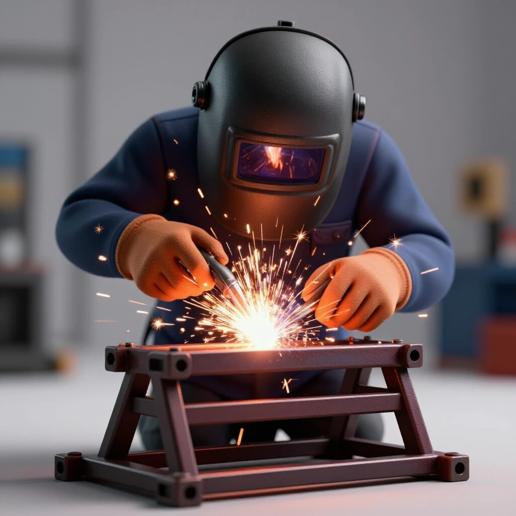
When you are constructing a rigid support for a small engine, you are building a tool that must handle weight and constant vibration. If the frame is not square, the engine will not sit flat, and the vibration will eventually crack your welds. This guide focuses on the technical reality of metal behavior. We will look at how to plan your cuts, set up workshop jigs and fixtures, and use specific weld sequencing layout strategies to keep your project straight and functional.
Planning Your Rigid Motor Support Structure
Effective planning for a workshop cradle involves creating a detailed cut list and accounting for the thickness of your cutting tool. This stage prevents material shortages and ensures that every piece of the frame fits together without gaps that cause weld failure.
Before you buy your steel, you need a blueprint. For a vibration-resistant base, I usually recommend 2-inch square tubing with a 1/8-inch or 3/16-inch wall thickness. Thinner material might be easier to cut, but it warps much faster under heat. I start by sketching the footprint of the engine and adding at least two inches of clearance on all sides. This gives me room for mounting bolts and hand tools.
Your cut list must be precise. If you need a frame that is 20 inches wide, and you are using 2-inch tubing, your cross-members should be 16 inches long if they sit between the side rails. I always write these numbers down on a whiteboard in the shop. It is too easy to forget a dimension once the sparks start flying and the noise of the grinder fills the room.
Accounting for Kerf and Achieving Accurate Square Cuts
Kerf is the material lost to the width of the saw blade during cutting. For a sturdy workshop cradle, failing to account for this 1/16 to 1/8 inch gap will result in a frame that is too small or joints that do not meet.
When I first started, I would mark a line and cut right down the middle of it. By the time I had made four cuts, my frame was nearly half an inch shorter than I intended. Now, I always “leave the line.” This means I position my blade so that the kerf is entirely on the scrap side of the mark. For a standard chop saw, the kerf is usually 1/8 inch. If you are using a portable band saw, it might be closer to 1/16 inch.
| Cutting Tool Type | Average Kerf Width | Dimensional Tolerance |
|---|---|---|
| Abrasive Chop Saw | 1/8″ (0.125 in) | +/- 1/16″ |
| Cold Saw | 3/32″ (0.094 in) | +/- 1/32″ |
| Portable Band Saw | 1/16″ (0.062 in) | +/- 1/32″ |
| Oxy-Acetylene Torch | 3/16″ (0.187 in) | +/- 1/8″ |
After cutting, every end must be square. I use a high-quality speed square to check the ends. If the cut is even slightly angled, the weld will pull the metal toward the gap. I spend more time at the disc sander cleaning up my cuts than I do welding. A clean, square joint is the only way to ensure a straight finished product.
Building Workshop Jigs for Frame Alignment
A jig is a temporary structure or clamp setup that holds your metal pieces in the exact position required for welding. Using fixtures ensures that the mounting base remains flat and square, even when the heat of the arc tries to pull it out of shape.
You do not need an expensive welding table to build a straight frame. I often use a flat section of my concrete garage floor or a heavy wooden workbench topped with a sheet of steel. The key is to create “stops.” These are small pieces of scrap metal or wood blocks screwed into the bench that the frame pieces can butt against.
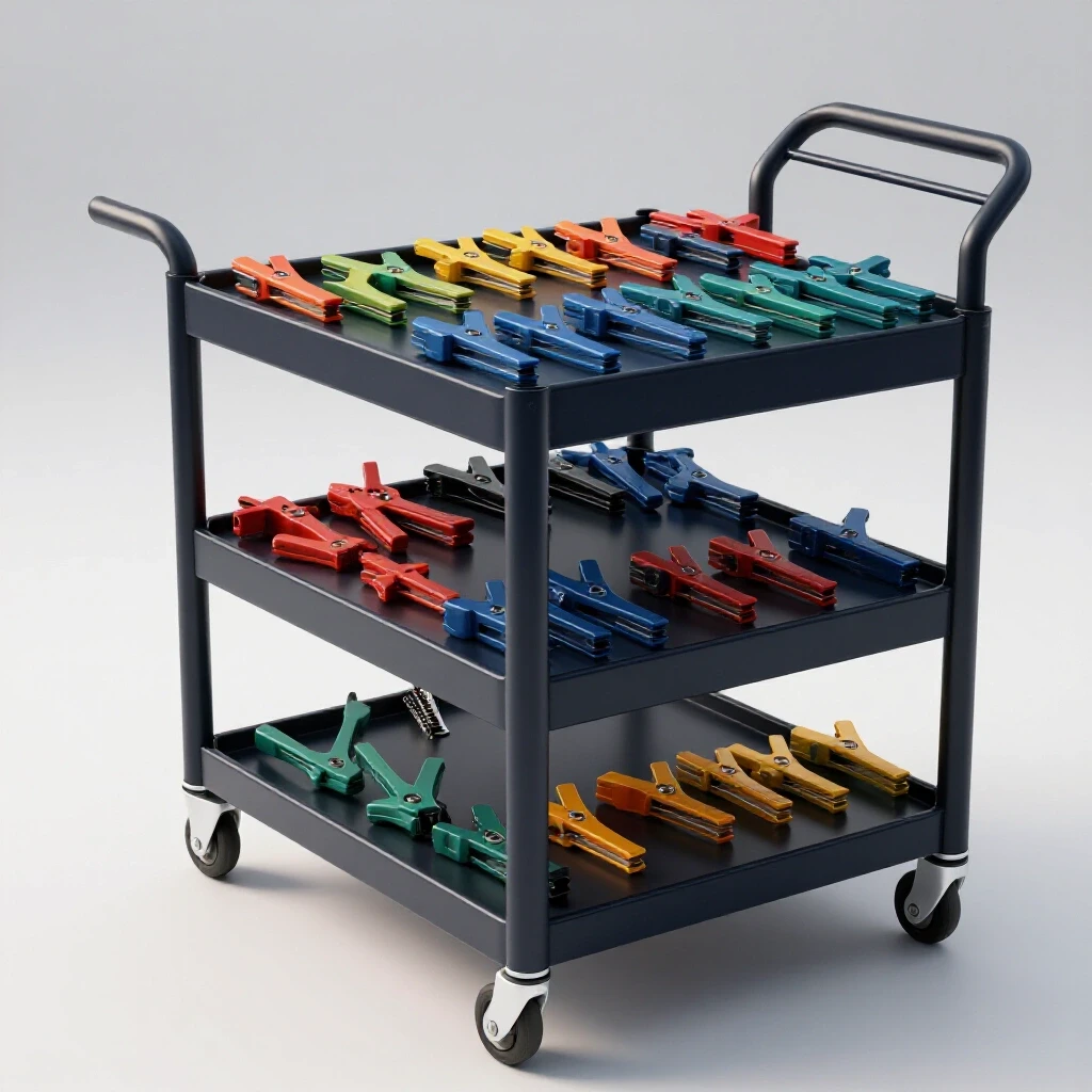
When setting up your workshop jigs and fixtures, use at least two clamps per joint. If you only use one, the metal can pivot. I prefer F-style clamps or heavy C-clamps. I also use a “squaring jig,” which is just two pieces of heavy angle iron welded together at a perfect 90-degree angle. I clamp my tubing into this jig before I ever pull the trigger on the welder. This physical restraint is your first line of defense against metal warping solutions.
Structural Tacking and Checking Geometry
Tack welds are small, temporary beads that hold the assembly together before the final passes. For a vibration-resistant frame, these tacks must be strong enough to resist heat pull but small enough to be incorporated into the final weld.
I use a “four-point tack” method for square tubing. I place one small tack in the center of each of the four sides of the joint. I never tack the corners first. Tacking the corners can cause the metal to “hinge” and pull the frame out of square. Each tack should be about 1/4 inch long.
Once the frame is tacked, I check the diagonals. I measure from the top-left corner to the bottom-right, then from the top-right to the bottom-left. If the measurements are within 1/16 of an inch, the frame is square. If they are off, I can usually “cold-set” the frame by bumping it against the floor or using a heavy mallet to nudge it into place before the final welding begins.
- Tack Spacing: One tack per side of the tubing.
- Tack Size: 1/4 inch for 1/8-inch wall material.
- Check Step: Measure diagonals after every four tacks.
- Tolerance: Aim for +/- 1/16 inch across the diagonals.
Why Weld Shrinkage Warps Square Structures—And the Precise Order to Lay Your Beads
When steel cools, it shrinks and pulls the surrounding metal toward the center of the weld. By following a specific sequence—welding opposite corners and alternating sides—you can balance these forces and keep the engine cradle straight.
This is where most DIY builders run into trouble. If you weld a complete joint from start to finish, the heat buildup will pull the metal toward that joint. I use a weld sequencing layout that distributes heat evenly across the entire frame. I never weld two joints that are right next to each other.
Think of it like tightening the lug nuts on a car wheel. You go in a star pattern. I weld the outside of the front-left corner, then the outside of the back-right corner. Then I move to the front-right and finally the back-left. By the time I return to the first corner, it has had time to cool. This “skipping” technique prevents any one area from getting so hot that it loses its structural integrity and warps.
| Weld Step | Location | Side of Joint | Purpose |
|---|---|---|---|
| 1 | Corner A | Outside Face | Establish outer boundary |
| 2 | Corner C (Diagonal) | Outside Face | Balance the first pull |
| 3 | Corner B | Outside Face | Distribute heat to new area |
| 4 | Corner D (Diagonal) | Outside Face | Finalize outer perimeter |
| 5 | Corner A | Inside Face | Counteract Step 1 |
Managing Heat Input and Angular Pull
Angular pull occurs when the top of a weld cools and shrinks faster than the bottom, causing the metal to “fold” toward the bead. To minimize this in your custom fabrication projects, you must control your travel speed and voltage settings.
I see many beginners turn their wire speed up too high, thinking more metal equals a stronger joint. In reality, too much metal just adds more heat, which leads to more warping. I set my machine so the bead is flat or slightly convex. If the bead is “humped” up high, it has too much internal tension.
I also use heat sinks when possible. A thick piece of copper or even a heavy scrap of aluminum clamped near the weld zone can soak up excess heat. This keeps the heat-affected zone (HAZ) small. The smaller the HAZ, the less the metal will move. If I notice the steel turning a deep blue or purple more than an inch away from the weld, I know I am moving too slowly or my heat is too high.
Correcting Distortion and Final Straightening Techniques
Even with the best planning, some movement is inevitable due to the physics of thermal expansion. Final adjustments involve using heat or mechanical force to bring the mounting rails back into a flat plane for the engine.
If I finish a frame and find it has a slight “rock” when sitting on a flat surface, I don’t panic. There are two ways to fix this: mechanical force and heat shrinking. For a heavy-duty frame, I might use a large C-clamp to pull the high corner down to my table and then “stress relieve” the opposite weld by hitting it with a hammer. This sounds crude, but it works.
Heat shrinking is a more advanced technique. I use an oxy-acetylene torch to heat a small spot on the side opposite the warp. When that spot cools, it shrinks and pulls the frame back. However, you must be careful. It is very easy to overcorrect and end up with a frame that is worse than when you started. I always try mechanical straightening first.
- Identify the high point: Place the frame on a known flat surface.
- Clamp the frame: Secure the three points that are touching the table.
- Apply pressure: Use a jack or a heavy clamp to push the fourth corner into place.
- Check for “spring back”: Release the clamp and see if the frame stays.
- Repeat as needed: Small increments are better than one large, forceful move.
Metal Layout Tips for Mounting Holes
Once the frame is straight, you need to drill the holes for the engine mounting bolts. Accuracy here is just as important as the welding. If your holes are off by even 1/8 inch, you will be forced to “slot” them with a grinder, which weakens the mount.
I never rely on a tape measure for mounting holes. Instead, I use a transfer punch or make a template out of thin cardboard. I set the engine (or a template of its base) onto the frame and mark the exact centers. I use a center punch to create a deep divot so the drill bit doesn’t wander.
I always drill a small pilot hole first, usually 1/8 inch. Then I follow up with the final size. For a vibration-heavy environment, I use Grade 5 or Grade 8 bolts with nylon-insert lock nuts. The frame is only as good as the hardware holding the engine to it.
Actionable Framework for a Successful Build
To keep yourself on track, follow this checklist. It will help you avoid the common mistakes that lead to a warped or crooked project.
- Verify Material: Check square tubing for “mill twist” before cutting.
- Clean the Steel: Remove all mill scale and oil within two inches of every joint.
- Double-Check Cuts: Ensure every piece is within 1/32 inch of the plan.
- Fixture Tight: Use at least 8 clamps for a simple rectangular frame.
- Tack Sequence: Top, bottom, then sides of each tube.
- Weld Sequence: Never weld two adjacent sides of a joint consecutively.
- Cooling Time: Let the frame air-cool; never quench it with water, which makes the steel brittle.
- Final Inspection: Measure diagonals one last time before declaring the project finished.
Conclusion
Building a heavy-duty support structure is a test of patience and technique. By respecting the way metal reacts to heat, you can move from “guessing” to “fabricating.” Remember that the most important tools in your shop aren’t just your welder and saw; they are your square, your clamps, and your willingness to slow down. If you focus on accurate square cuts and a disciplined weld sequencing layout, you will produce a frame that is professional, durable, and perfectly suited for your needs.
FAQ
Why does my frame always pull out of square even when I use clamps? Clamps can hold the metal in place, but they cannot stop the internal molecular shrinkage of the cooling weld. If you weld one side completely, the force of the shrinkage is often stronger than the clamp’s grip. You must balance the pull by welding in short sections on opposite sides of the frame.
What is the best way to check for squareness if I don’t have a large square? The most accurate method is the “3-4-5 rule” or checking diagonals. Measure from opposite corners. If the frame is a perfect rectangle, the diagonal measurements will be identical. Even a tiny difference in these numbers indicates the frame is a trapezoid rather than a square.
Should I weld the inside or the outside of the joints first? Always start with the outside faces. This creates a rigid outer perimeter. If you weld the inside corners first, the “angular pull” will draw the rails inward, making the frame narrower than you intended.
How many tack welds are really necessary? For 2-inch square tubing, four tacks are the standard. One in the center of each flat face. This prevents the tube from pivoting or “opening up” like a book as the metal expands.
Can I use a magnet to hold the pieces at 90 degrees? Magnets are great for a quick “third hand,” but they are not strong enough to resist the movement of a cooling weld. Always follow up a magnetic setup with mechanical clamps before you start your final beads.
What happens if I quench the welds with water to speed up cooling? Never do this. Rapid cooling with water changes the grain structure of the steel, making it extremely hard and brittle. In a high-vibration environment like an engine stand, a quenched weld is much more likely to snap or develop stress cracks.
How do I handle “mill scale” on the steel? Mill scale is the dark, flaky coating on hot-rolled steel. You must grind this off down to shiny metal wherever you plan to weld. Welding over mill scale causes arc instability and leads to “porosity,” which are tiny holes in the weld that weaken the structure.
What is the ideal gap between pieces before welding? For most DIY projects using MIG welding on 1/8-inch material, a “tight fit” (no gap) is usually best to prevent excessive warping. However, if you are using a lower-powered welder, a 1/16-inch gap can help ensure full heat penetration through the thickness of the metal.
Is square tubing better than angle iron for an engine base? Square tubing is significantly more resistant to twisting (torsion) than angle iron. For a heavy-duty frame that needs to handle vibration, square or rectangular tubing is almost always the superior choice.
How do I stop the drill bit from “walking” when I make mounting holes? Use a center punch to create a physical indentation in the steel. Then, use a small pilot bit (about 1/8″) at a high RPM with light pressure. Once the pilot hole is through, switch to your larger bit at a lower RPM with more pressure and cutting oil.
(This article was written by one of our staff writers, Robert Kline. Visit our Meet the Team page to learn more about the author and their expertise.)