Is ER70S-6 MIG Welding Wire Better for Rusty Steel? (Review)
I spent my first three years in the shop wondering why my beads looked like Swiss cheese whenever I worked on anything other than brand-new, shiny metal. I would adjust my voltage, crank up the wire speed, and hold my breath, but the results were always the same: popping, sputtering, and tiny holes in the weld. It took me a long time to realize that my physical technique was only half the battle. The other half was understanding how the chemistry of my consumables interacted with the condition of my steel.
When I started tracking my progress in a dedicated shop log, I noticed a pattern. My consistency improved significantly when I switched to a wire with higher deoxidizer levels. For a self-taught fabricator, the learning curve is steep enough without fighting the metal itself. If you are currently struggling with erratic bead shapes or inconsistent penetration on material that isn’t perfectly clean, understanding the specific properties of the wire in your machine is a vital step in your progression.
The Role of Chemical Deoxidizers in Solid MIG Wire
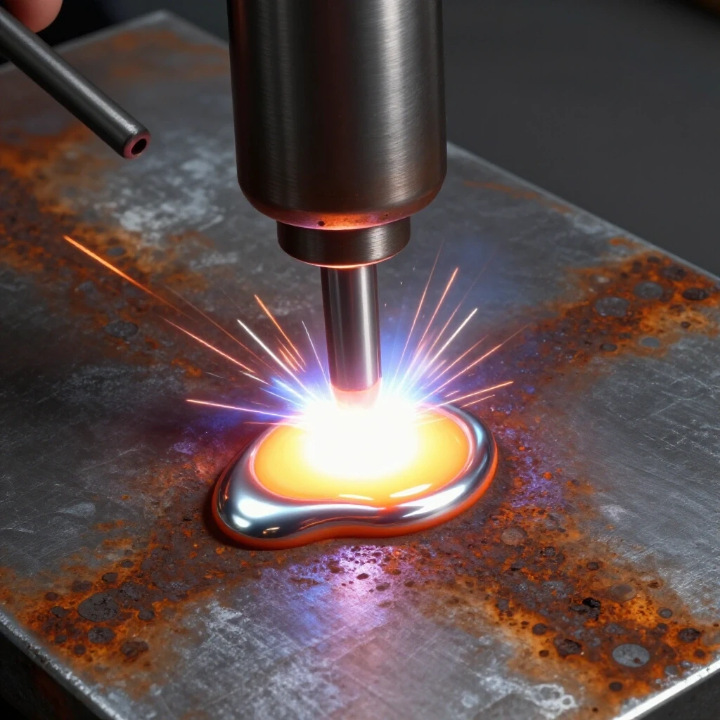
Solid MIG wire chemistry determines how the molten puddle reacts to oxygen and surface impurities during the welding process. High-silicon wires like ER70S-6 are designed with extra manganese and silicon to act as cleaning agents, pulling light oxides to the surface of the weld bead.
To understand why some wires handle surface scale better than others, we have to look at the American Welding Society (AWS) classification. In the code ER70S-6, the “ER” stands for electrode or rod, the “70” represents a minimum tensile strength of 70,000 psi, and the “S” means it is a solid wire. The “6” is the most important part for us. It indicates a higher level of silicon and manganese compared to the common ER70S-3 wire.
These elements are known as deoxidizers. When you strike an arc on steel that has a thin layer of mill scale or light surface rust, oxygen is released into the puddle. This oxygen can cause porosity, which is essentially tiny gas bubbles trapped in the metal. The silicon and manganese in the wire react with that oxygen first, forming a thin, glassy slag on top of the bead. This protects the structural integrity of the weld and helps the puddle flow more smoothly.
Identifying Surface Contaminants on Mild Steel
Surface contaminants like mill scale, light rust, and oil can interfere with the electrical conductivity and chemical balance of a weld. While certain wires are more forgiving, knowing the difference between “weldable” surface conditions and “critical failure” zones is essential for any fabricator.
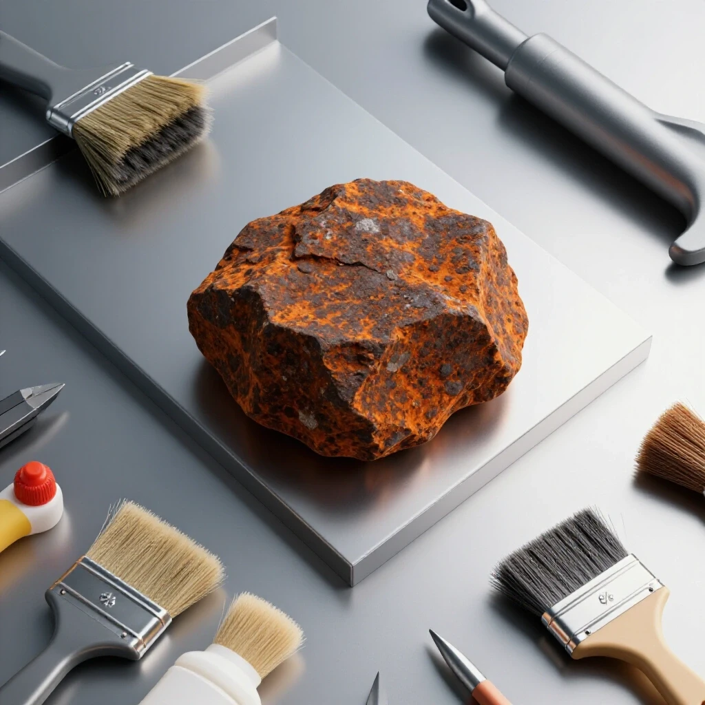
In my early practice sessions, I often ignored mill scale, that dark blue-grey coating found on hot-rolled steel. I assumed the heat of the arc would just burn it away. However, mill scale is an oxide layer that is much harder than the base steel. It has a higher melting point, which can lead to “cold lap” where the weld sits on top of the metal instead of fusing into it.
Light surface rust is another common hurdle. If the rust is just a thin, orange dusting that doesn’t pit the metal, a high-deoxidizer wire can usually handle it. However, if the rust is “structural”—meaning it is flaking off or has created deep pits—no wire in the world will save that joint. You must mechanically clean the steel back to a bright, shiny finish. I always teach my students the “one-inch rule”: clean at least one inch of bare metal on either side of the joint to ensure the arc stays stable.
| Contaminant Type | Appearance | Impact on Weld | Recommended Action |
|---|---|---|---|
| Mill Scale | Dark blue/grey, smooth | Lack of fusion, arc wandering | Grind to bright metal |
| Light Surface Rust | Thin orange dust | Minor porosity, sputtering | Use high-silicon wire |
| Heavy Pitted Rust | Flaking, deep texture | Severe porosity, structural failure | Replace material or deep grind |
| Shop Oils | Clear or yellowish film | Hydrogen cracking, wormholes | Wipe with acetone/degreaser |
Physical Mechanics and Torch Control for Consistent Beads
Mastering the physical movement of the torch requires developing muscle memory through repetitive, structured practice. Consistency in your travel speed, work angle, and electrode stick-out is the foundation of a professional-grade weld, regardless of the wire type being used.
When I was learning to control the puddle, I found that my hand-eye coordination improved fastest when I focused on my body positioning. You cannot move smoothly if you are tensed up or reaching too far. I use what I call the “tripod method.” I keep my dominant hand on the torch trigger, and I use my non-dominant hand to steady the neck of the torch, often resting my pinky or the side of my palm on the work table.
The three most critical physical metrics to track in your practice log are:
- Work and Travel Angles: For a standard flat bead, I maintain a 10 to 15-degree drag angle. This means the top of the torch is tilted slightly back toward the direction I just came from. This pushes the gas and the heat into the puddle, helping the deoxidizers do their job.
- Electrode Stick-out: Keep your wire protruding about 3/8 of an inch from the contact tip. If the wire is too long, the gas coverage weakens, and the wire becomes too hot before it hits the puddle. If it is too short, you risk fusing the wire to the contact tip.
- Travel Speed: This is where most beginners fail. I aim for a speed of 8 to 12 inches per minute (IPM). If you go too fast, the bead becomes thin and “ropey.” If you go too slow, you build up too much heat, which can lead to burn-through or excessive distortion.
Parameter Mapping for Consistency
Setting the correct voltage and wire feed speed (WFS) on your machine is a technical skill that requires an understanding of how heat input affects the metal. Mapping these parameters allows you to recreate successful welds and troubleshoot failures with data rather than guesswork.
Every machine has a slightly different “sweet spot.” When using a high-silicon wire on steel with light scale, you may need a slightly higher voltage than you would on perfectly clean metal. This extra heat helps the deoxidizers react faster and allows the puddle to wet out against the edges of the joint.
I recommend a “step-up” practice drill. Start with the manufacturer’s suggested settings for your material thickness. Run a three-inch bead. Stop, let it cool, and look at the profile. Is it too tall? Increase your voltage or slow down your travel speed. Is it too flat or wide? Decrease your voltage or speed up. By changing only one variable at a time and recording the results, you will build a personal “parameter map” that is far more accurate than any chart on the inside of a welder door.
- Voltage (V): Controls the width and “fluidity” of the puddle.
- Wire Feed Speed (WFS): Controls the amperage and the depth of penetration.
- Inductance (if available): Controls how fast the short-circuit cycle happens, which can reduce spatter when welding over light oxidation.
Structured Practice and Progression Cycles
Systematic improvement in fabrication comes from breaking down complex movements into simple, repeatable drills. By isolating specific variables like joint type or material condition, you can identify exactly where your technique is breaking down and address it.
When I work with intermediate students, we follow a strict progression. We don’t move to the next step until the current one is mastered. This prevents the frustration of “plateauing” where you feel like you aren’t getting any better despite spending hours in the shop.
Step 1: Bead-on-Plate (The Foundation)
Take a flat piece of 1/8-inch mild steel. Draw straight lines with a soapstone or silver pencil. Practice running straight beads without any weaving. Focus entirely on maintaining a consistent 3/8-inch stick-out and a steady 10-degree drag angle. Your goal is a bead that is uniform in width and height from start to finish.
Step 2: The Lap Joint
Overlay two pieces of steel. This introduces the challenge of managing heat between two different edges. You must point the wire more toward the bottom plate to prevent the top edge from melting away too quickly. This drill teaches you “puddle manipulation”—watching how the molten metal flows into the corner.
Step 3: The Fillet Weld (T-Joint)
This is the most common joint in fabrication. It requires a 45-degree work angle. If you are using a high-silicon wire on mill-scaled steel, you will notice the slag islands forming in the center of the bead. Practice keeping your arc at the leading edge of the puddle to ensure you are penetrating the root of the joint.
Troubleshooting Common Technique Errors
Even with the best wire and settings, physical errors can lead to weld defects. Learning to read the “story” told by a finished bead is the best way to correct your habits. I always keep a magnifying glass and a bright light at my workbench to inspect my practice coupons.
One common issue is porosity. If you see tiny holes, check your gas flow (usually 20-25 CFH) and your stick-out length. If the gas is fine, you might be moving the torch too fast, leaving the puddle exposed to the air before it can solidify. Another issue is undercut, which looks like a small groove or “valley” at the toe of the weld. This is usually caused by having your voltage too high for your travel speed, or an incorrect torch angle that “washes” the metal away from the edge.
Practice Log Template for Skill Tracking
To measure your progress objectively, you must record your sessions. I have used a version of this template for over a decade. It turns “messing around in the shop” into “vocational training.”
- Date and Session Goal: (e.g., Oct 12 – Master 2F Fillet Weld on 3/16″ Plate)
- Material Prep: (e.g., Ground to bright metal, left mill scale on, etc.)
- Consumables: (e.g., .030 ER70S-6, 75/25 Argon/CO2)
- Machine Settings: (e.g., 18.5V, 240 WFS)
- Physical Metrics: (e.g., 10-degree drag, 1/2″ stick-out)
- Visual Assessment: (e.g., Bead was too convex, suggests travel speed was too slow)
- Correction for Next Run: (e.g., Increase travel speed by 10%)
Advancing Your Skills with Modern Tools
In the modern shop, we have access to tools that make self-correction much easier. I highly recommend using your smartphone to record your welding sessions. Set up a tripod and film your hand movement and the arc. When you watch the footage in slow motion, you will see things you missed while under the hood.
You might notice that your hand shakes slightly at the end of a long run, or that your torch angle changes as you move across the plate. There are also digital parameter calculators available as apps that can give you a solid starting point for your voltage and WFS based on the specific wire chemistry you are using. These tools don’t replace practice, but they do make your practice much more efficient.
The path to becoming a skilled fabricator is paved with thousands of inches of weld beads. By choosing a wire that complements the reality of your material—like the high-silicon ER70S-6—and following a structured, data-driven practice routine, you can overcome the plateaus that stop so many beginners. Focus on your body mechanics, respect the chemistry of the metal, and keep your logbook updated. The consistency you are looking for is just a few hundred practice coupons away.
Frequently Asked Questions
Does using a high-silicon wire mean I never have to grind my steel? No. While wires like ER70S-6 are better at handling light surface oxidation and mill scale, they are not a replacement for mechanical cleaning. For any structural or high-quality weld, you should still grind the joint to bright metal. The deoxidizers are there to provide a safety margin against microscopic impurities, not to weld through heavy rust or paint.
How can I tell if my travel speed is correct? A good rule of thumb is the “bead width” test. For most MIG applications, your bead should be about 2 to 3 times the diameter of the wire. If you are using .035 wire, your bead should be roughly 1/8 to 3/16 of an inch wide. If it is wider, you are moving too slowly; if it is narrower, you are moving too fast.
Why does my weld have brown “glassy” spots on top? Those are slag islands created by the silicon and manganese deoxidizers. They are actually a sign that the wire is doing its job. These islands pull impurities out of the weld pool and deposit them on the surface. They should be easily removed with a wire brush or chipping hammer.
What is the best gas to use with high-deoxidizer solid wire? A 75% Argon and 25% CO2 mix (C25) is the industry standard for short-circuit MIG on mild steel. It provides a good balance of puddle fluidity and minimal spatter. Using 100% CO2 is cheaper and provides deeper penetration, but it will result in more spatter and a rougher bead appearance.
Can I use ER70S-6 on thin sheet metal? Yes, it is excellent for thin material because the silicon helps the puddle “wet out” at lower temperatures. This allows you to get a flatter bead without needing excessive heat, which reduces the risk of warping or burning through the sheet.
How do I stop my contact tip from constantly “burn-backing”? Burn-back usually happens because your wire feed speed is too low for your voltage, or your stick-out is too short. Try increasing your WFS slightly or holding the torch a bit further away from the work. Also, ensure your ground clamp is on a clean piece of metal to prevent arc fluctuations.
Is there a difference in shelf life for different MIG wires? Solid wire can rust if left in a damp environment. Since ER70S-6 is often copper-coated, it has some resistance to moisture, but you should still store it in a dry place. If you see any rust on the wire itself, do not use it, as it will feed rust directly into your weld and cause major porosity.
Why is my arc making a loud “pop” sound instead of a consistent hiss? A loud popping or “machine gun” sound usually indicates that your wire feed speed is too high, causing the wire to hit the bottom of the puddle before it can melt. This is called “stubbing.” Turn your WFS down or increase your voltage to achieve a smooth, consistent “frying bacon” sound.
How often should I change my contact tip? You should change it whenever the hole becomes “egged out” or if you notice the arc wandering. A worn tip can cause poor electrical contact, leading to an unstable arc. In a practice environment, a tip should last through several 10-pound rolls of wire if you maintain proper stick-out.
What is the “push” vs. “pull” technique? “Pushing” (forehand) involves pointing the torch away from the weld, while “pulling” (backhand/drag) involves pointing it toward the weld. Dragging generally provides deeper penetration and is better for handling surface contaminants because the arc stays at the front of the puddle, allowing the deoxidizers more time to work.
(This article was written by one of our staff writers, Thomas Langley. Visit our Meet the Team page to learn more about the author and their expertise.)