How to Use Aluminum Heat Sinks for Thin Steel Welds (Tips)
I have spent over 15 years in fabrication shops, and few things are as frustrating as watching a thin steel panel warp into a potato chip the moment you strike an arc. You have spent hours on the layout, the cuts are precise, and your machine settings seem perfect. Then, the heat takes over. The metal moves, the joint opens up, and suddenly you are fighting a losing battle against physics. In my experience, these moments are where many fabricators lose their cool. They start chasing settings on the welder or swapping out shielding gas, but the root cause is rarely the machine. It is thermal management.
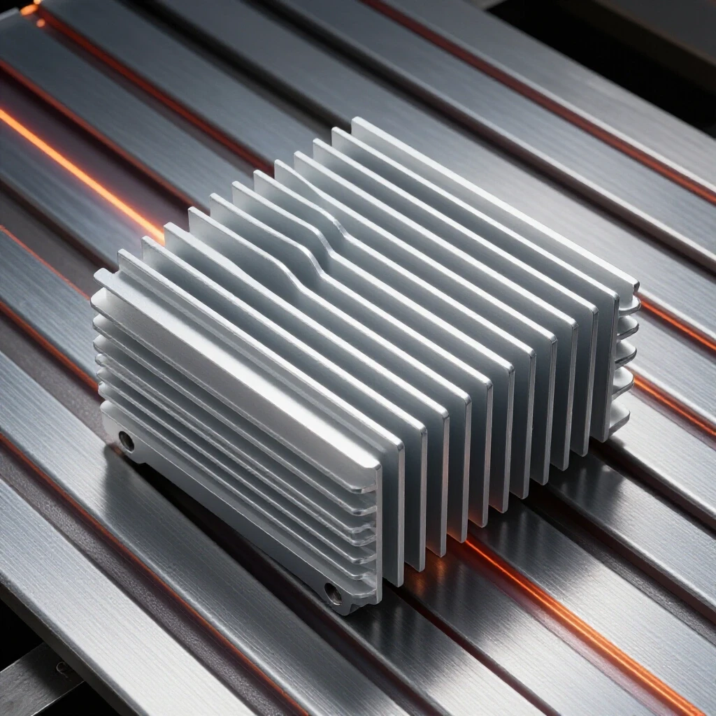
When I first started troubleshooting industrial fabrication lines, I saw this play out on 20-gauge stainless and mild steel assemblies. We were seeing a 30% rejection rate due to distortion and burn-through. The solution wasn’t a more expensive welder; it was a systematic approach to heat control using aluminum. Aluminum serves as a thermal sponge. Because its thermal conductivity is significantly higher than steel, it can pull heat away from the weld zone before the steel has a chance to expand and deform. This metalworking diagnostic guide will walk you through the precise steps to integrate these tools into your workflow to solve the “hard-to-find” issues of warping and blow-through.
Understanding the Thermal Dynamics of Thin Steel
Thermal dynamics in welding refers to how heat moves through a material and the resulting physical changes, such as expansion and contraction. In thin steel, the lack of mass means heat accumulates quickly, leading to a high risk of structural deformation or melting through the base metal.
In my repair logs, I often categorize thin steel as anything under 1/8 inch, but the real trouble starts at 16 gauge (0.059 inches) and thinner. Steel has a relatively low thermal conductivity, roughly 45 to 50 Watts per meter-Kelvin (W/m·K). When you apply a TIG or MIG arc, that heat stays localized. Since it cannot move away quickly, the temperature spikes. This causes the metal to expand in a very small area while the surrounding metal remains cool and rigid. The result is a mechanical “fight” within the sheet that ends in a buckle or a twist.
To fix this, we look at the thermal properties of the tools we use. Aluminum 6061, a common shop staple, has a thermal conductivity of about 167 W/m·K. That is more than triple the rate of steel. By placing an aluminum block behind or beside your weld, you create a path of least resistance for that energy. I have found that using these blocks effectively acts like a “heat sink” in electronics, keeping the base metal below its critical deformation temperature. This is a fundamental step in any systematic metal fabrication fix.
Why Thin Steel Warps and How to Isolate the Cause
Warping is the result of non-uniform expansion and contraction during the heating and cooling cycles of welding. Isolating the cause involves checking material thickness, heat input (amperage), and the speed at which the welder moves the arc.
When a reader asks me why their welds are pulling, I start with a diagnostic framework. First, we observe the pattern of the warp. Is it a long, sweeping curve, or a series of small “oil cans” (localized buckles)?
- Long curves usually indicate a lack of tack welds or excessive continuous heat.
- Localized buckles often mean the amperage is too high for the travel speed.
I once worked on a project involving 22-gauge cold-rolled steel cabinets. The fabricator was using 45 amps on a TIG setup, but the panels were still waving. We used an infrared thermometer to track the heat-affected zone (HAZ). We discovered the heat was soaking into the panel for three inches on either side of the seam. By clamping a 1/2-inch thick aluminum bar 1/8-inch away from the joint, we reduced that HAZ to less than half an inch. The warping stopped immediately. This is a classic example of using isolation to identify that the issue was heat dissipation, not the welding technique itself.
Selecting the Right Aluminum Grade for Thermal Control
Selecting the right aluminum involves choosing a grade and thickness that can handle the thermal load without melting or sticking to the steel. The material must be thick enough to act as a reservoir for the heat being pulled from the weld.
For most shop environments, 6061-T6 aluminum is the standard choice. It is affordable, readily available, and has excellent thermal properties. I recommend using blocks that are at least 3/8-inch to 1/2-inch thick. If the aluminum is too thin, it will heat up too quickly and lose its ability to pull energy from the steel.
I have seen people try to use thin aluminum flashing or scraps, but these often fail. A thin piece of aluminum will reach thermal saturation in seconds. Once it is as hot as the steel, the heat transfer stops. In my troubleshooting process, I always check the mass of the sink. A good rule of thumb is that the aluminum should be at least four times the thickness of the steel you are welding. If you are working on 18-gauge steel (0.047 inches), a 1/4-inch aluminum bar is your baseline.
Troubleshooting Surface Contact and Mechanical Alignment
Surface contact refers to the physical gap between the aluminum sink and the steel workpiece. Mechanical alignment ensures that these two surfaces are perfectly flush to allow for maximum heat transfer through conduction.
If there is even a 0.005-inch gap between your aluminum block and your steel, the heat sink will fail. Air is a terrible conductor of heat. I have diagnosed many “failed” heat sinks only to find that the aluminum bar was slightly bowed or the steel had a burr on the underside.
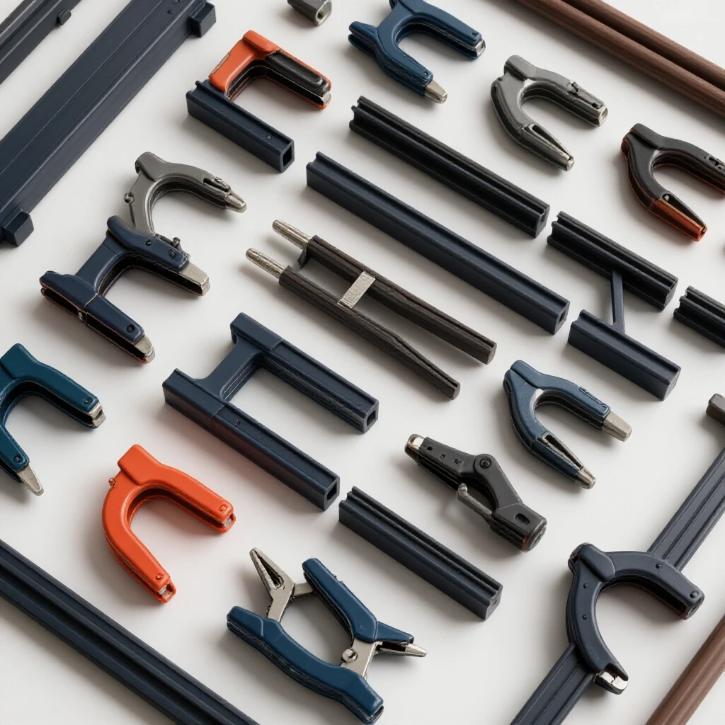
To resolve this, I use a systematic checklist: 1. Check for Flatness: Use a straightedge or a digital dial indicator to ensure the aluminum block is flat within 0.002 inches. 2. Clean the Surfaces: Remove all mill scale, rust, or oils from the steel. Aluminum should be cleaned with a dedicated stainless steel wire brush to remove the oxide layer. 3. Apply Clamping Pressure: Use C-clamps or toggle clamps every 4 to 6 inches. The goal is to “sandwich” the steel so there is zero visible light between the materials.
In a case study involving thin-walled steel tubing, we were getting inconsistent penetration. We found that the roundness of the tube varied by 0.010 inches, preventing the aluminum “V-block” sink from making contact. By switching to a flexible aluminum strap-style sink, we restored contact and eliminated the burn-through.
Positioning Strategies for Maximum Heat Extraction
Positioning involves the strategic placement of the aluminum relative to the weld bead. This can be directly behind the weld (backing bar) or adjacent to it (chill bar) depending on the joint type.
There are two primary ways I use aluminum to solve heat issues:
- Backing Bars: This is placed directly under the butt joint. It supports the molten puddle and prevents it from falling through (burn-through). Because aluminum has a much higher melting point than the temperatures reached in low-amperage steel welding, the steel won’t stick to it.
- Chill Bars: These are clamped on the top side, parallel to the weld seam. They are usually placed about 1/16 to 1/8 of an inch away from the edge of the joint. They “suck” the heat out of the sheet before it can migrate into the rest of the panel.
| Diagnostic Factor | Backing Bar Strategy | Chill Bar Strategy |
|---|---|---|
| Primary Goal | Prevent burn-through | Limit distortion/HAZ |
| Placement | Directly under the seam | 1/8″ away from the seam |
| Clamping Needs | High (must support puddle) | Moderate (must stay flush) |
| Common Issue | Arc blow if magnetized | Obstruction of torch angle |
Managing Amperage and Travel Speed with Sinks
Amperage is the electrical current flow that creates the heat, while travel speed is how fast the torch moves. When using a heat sink, these variables must be adjusted because the sink is actively removing the energy you are trying to use to melt the metal.
One of the biggest mistakes I see advanced fabricators make is not adjusting their settings when they add aluminum. Because the aluminum is so efficient, it can actually “chill” the weld too much. This leads to a lack of fusion or a “cold” weld bead that sits on top of the metal rather than penetrating it.
When I am troubleshooting a cold weld with a heat sink, I usually increase my starting amperage by 10% to 15%. For 18-gauge mild steel, I might move from 50 amps to 58 amps. However, you must maintain a fast travel speed. The aluminum gives you a “buffer” that allows you to use more heat for better penetration without the risk of the metal sagging or warping. It is a delicate balance. If you see the weld puddle becoming sluggish, you are likely losing too much heat to the sink. In that case, increase your amperage or move the chill bars slightly further away.
Diagnosing Weld Porosity and Gas Coverage Near Sinks
Weld porosity is the presence of tiny holes or gas pockets in the weld bead, often caused by trapped contaminants or poor gas shielding. When using heat sinks, the physical presence of the block can sometimes interfere with the flow of shielding gas.
If you start seeing porosity after adding an aluminum sink, don’t immediately blame the gas bottle. I have found that large aluminum blocks can create “pockets” where the shielding gas (Argon or CO2/Argon mix) gets turbulent. Instead of a smooth, laminar flow over the puddle, the gas hits the edge of the aluminum block and swirls away, letting oxygen in.
To fix this, I look at the gas flow rate. If I am typically running 15 cubic feet per hour (CFH), I might bump it up to 20 CFH when using a thick chill bar. Also, check the torch angle. You may need to hold the torch more vertically to ensure the gas cup is “sealing” the area between the aluminum blocks.
- Symptom: Small pinholes at the start of the weld.
- Fix: Increase pre-flow time to 1.0 seconds to purge the area around the aluminum.
- Symptom: Black, “sooty” deposits.
- Fix: Clean the aluminum sink; it may be off-gassing oils or residues from previous jobs.
The Systematic Repositioning Method
Repositioning is the practice of moving the heat sink as the weld progresses to ensure that the area being welded always has a “cold” thermal reservoir nearby. This prevents the aluminum itself from becoming a heat source.
During a long weld on a thin steel seam, even a large aluminum block will eventually heat up. In my 18 years of troubleshooting, I’ve seen many fabricators wonder why the first six inches of a weld look perfect, but the last six inches are warped. The reason is thermal saturation. The aluminum has absorbed all the heat it can hold.
The fix is a “leapfrog” method. I use two or three smaller aluminum blocks instead of one long one. As I finish a section, I move the “cool” block from the beginning of the weld to the front of the welding direction. This ensures that the arc is always moving toward a cold sink. If you only have one block, you must stop, let the piece cool to the touch, and then resume. I use a “rule of touch”: if I cannot keep my gloved hand on the aluminum sink for five seconds, it is too hot to be effective.
Real-World Case Study: Resolving Distortion in 20-Gauge Steel Frames
I was called into a shop that was struggling with 20-gauge square tubing frames. They were TIG welding the mitered corners, and every frame was coming out 1/4-inch out of square. They tried heavy steel jigging, but the frames still pulled.
We diagnosed the issue as “shrinkage pull.” As the weld cooled, it contracted, pulling the miter inward. We replaced their steel jigs with custom-machined aluminum corner inserts. These inserts were 1-inch thick and fit snugly inside the tubing.
By using the aluminum inside the tube, we did two things: 1. We maintained the 90-degree mechanical alignment. 2. The aluminum pulled the heat out of the thin walls so fast that the “shrinkage” phase was minimized.
We measured the temperature of the steel 1/2-inch from the weld. With the steel jig, it reached 850°F. With the aluminum sink, it stayed below 400°F. The frames stayed within a 0.010-inch tolerance. This case study proves that the material of your fixture is just as important as the design of the fixture itself.
Maintenance and Calibration of Your Heat Sinks
Maintenance involves keeping the surfaces of your aluminum sinks clean, flat, and free of “arc strikes” or weld spatter. A damaged sink will not provide the uniform contact necessary for heat transfer.
You should treat your aluminum heat sinks like precision tools. If you drop one and nick the edge, that nick creates an air gap. I keep a dedicated file and a 400-grit sanding block in my kit just for dressing my aluminum bars.
- Inspect for Spatter: Even though steel doesn’t easily stick to aluminum, MIG spatter can sometimes “pepper” the surface. Scrape it off immediately.
- Check for Oxidation: Over time, aluminum develops a thick oxide layer. This layer actually has a different thermal profile. I lightly sand my sinks once a week if they are in heavy use.
- Monitor Flatness: Heat cycles can eventually warp the aluminum itself. Every few months, I put my sinks on a surface plate or a known flat table to check for “rocking.” If they aren’t flat, I mill them back to true.
Summary of Diagnostic Benchmarks for Thin Steel
When you are troubleshooting these issues, you need hard numbers. Guesswork is the enemy of productivity. In my shop, we use these benchmarks to ensure our heat management system is working.
- Thermal Gap: Maximum allowable gap between sink and steel is 0.005 inches.
- Sink Thickness: Minimum 4x the thickness of the base metal.
- HAZ Width: On 18-gauge steel, the heat-affected zone should not exceed 1/4 inch when using a sink.
- Cool-Down Time: If the aluminum reaches 200°F (tracked with an IR temp gun), stop and swap the sink or let it air cool.
- Amperage Adjustment: Expect to increase amperage by 10-15% to compensate for heat draw.
By following these metrics, you take the “magic” out of the process and replace it with a repeatable, scientific method. This reduces downtime and ensures that your first part is just as good as your hundredth.
FAQ: Using Aluminum Heat Sinks for Thin Steel
Will the aluminum melt or fuse to my steel weld? In low-amperage TIG or MIG welding (under 100 amps), the aluminum will not melt. Aluminum’s melting point is about 1,220°F, while steel is around 2,500°F. However, the aluminum’s high thermal conductivity keeps its own temperature well below its melting point because it spreads the heat so rapidly throughout its mass. It will not fuse to the steel because they are dissimilar metals with very different molecular structures.
Can I use aluminum sinks for MIG welding as well as TIG? Yes, aluminum sinks are highly effective for both. In MIG welding, the heat input is often more intense but shorter in duration. The aluminum sink is excellent at catching that “burst” of heat and preventing the common MIG issue of blowing a hole through the start of a thin steel seam.
How do I keep the aluminum sink in place on a curved surface? For curved surfaces, I use annealed aluminum strips that can be slightly bent to match the radius, or I machine a “negative” of the curve into a thick aluminum block. Secure contact is the priority; if you can’t get it flush, it won’t work.
What should I do if the weld is “sinking” into the aluminum? If the steel is actually sagging and taking the shape of the aluminum, you are likely using too much amperage or moving too slowly. The aluminum is there to support the puddle, not to let the steel “mold” to it. Back off your heat or speed up your travel.
Does the grade of aluminum really matter? While 6061 is the most common, almost any solid aluminum will work better than steel for heat dissipation. Avoid “cast” aluminum scrap if possible, as it can contain air pockets that act as thermal insulators. Stick to 6000 or 7000 series extruded or rolled plate for the best results.
How do I prevent “arc blow” when using a heat sink? Aluminum is non-magnetic, so it does not cause arc blow. In fact, using an aluminum sink can sometimes help stabilize an arc that is being affected by nearby magnetic steel fixtures. If you are experiencing arc blow, the cause is likely your ground clamp placement or magnetism in the steel itself, not the aluminum.
Can I use water-cooled aluminum blocks? For most manual fabrication, water-cooling is overkill and adds unnecessary complexity. A solid block of 1/2-inch aluminum has enough “thermal mass” to handle several feet of welding on thin gauge steel before it needs to cool down.
Should I use a heat-sink compound or grease between the aluminum and steel? No. While thermal paste is used in electronics, it will contaminate your weld and cause massive porosity and structural failure in the steel. Always keep the contact surfaces clean and dry. Rely on mechanical clamping pressure to bridge the gap.
How close should the aluminum be to the actual weld bead? For a backing bar, it should be directly underneath. For chill bars on the top side, I find that 1/8 of an inch is the “sweet spot.” If it is too close, you risk the arc jumping to the aluminum or the block obstructing your view. If it is further than 1/4 inch, the heat has too much room to spread before it hits the sink.
Is there a limit to how thin the steel can be? I have successfully used aluminum sinks on steel as thin as 0.015 inches (shim stock). At those levels, the aluminum is the only thing keeping the metal from vaporizing. The thinner the steel, the more critical the “zero-gap” contact becomes.
(This article was written by one of our staff writers, Paul Whitaker. Visit our Meet the Team page to learn more about the author and their expertise.)