Standardized Assembly Guides for Custom Metal Builds (Check)
Scaling a fabrication shop from a hobby space into a semi-professional operation is a transition marked by both excitement and significant stress. I remember the day I realized my original shop layout was no longer working. I was tripping over drops of steel, my single-phase compressor was screaming to keep up with a new air tool, and I spent more time looking for my square than actually welding. It was a classic production bottleneck. Over the last 20 years, I have learned that scaling up isn’t just about buying bigger tools; it is about creating a system where those tools can actually perform.
When you move toward advanced fabrication, you are essentially becoming a process engineer. You have to look at your floor space as a high-value asset. Every foot of movement by a fabricator costs money. Every minute a CNC plasma table sits idle because of a power issue or a layout conflict is a hit to your bottom line. My goal is to help you navigate these hurdles by applying lean manufacturing principles to your specific environment. We will look at how to organize your space, manage your power, and create repeatable assembly protocols that ensure your custom projects are built safely and efficiently every time.
Mapping the Physical Path of Custom Fabrication
A workshop layout involves the strategic placement of machinery, workbenches, and material storage to minimize movement and maximize throughput. It is the foundation of a lean workflow, ensuring that raw materials move from the entry point to the finished product with the least amount of resistance.
In my early years, I had a “spaghetti” workflow. If you traced my steps with a red marker, the floor would have been solid red. I would move a sheet of steel from the rack to the floor, then to the saw, then back to a table. To fix this, you need to think about material travel paths. Ideally, your shop should follow a U-shaped or linear flow. Raw material comes in one door, moves through the cutting station, moves to the fabrication tables, enters the welding zone, and finally hits finishing and shipping.
Why Back-and-Forth Foot Traffic Kills Shop Throughput
Linear flow patterns are layout designs that prioritize a one-way movement of materials through different stages of production. By reducing the need for fabricators to backtrack or cross paths, you eliminate physical bottlenecks and reduce the risk of accidents in a crowded shop.
When I redesigned my 1,500-square-foot shop, I measured my “travel waste.” I found that by simply moving my cold saw closer to the material rack, I saved nearly two miles of walking per month. For an advanced shop, you should aim for a 3-foot minimum access zone around every major machine. This isn’t just for safety; it allows for maintenance and easier material handling. If you are integrating a CNC plasma table setup, you need to account for the “swing zone” of the gantry and the space required to load a full 4×8 sheet without hitting a support post or another machine.
| Layout Type | Material Travel Distance | Efficiency Rating | Best For |
|---|---|---|---|
| Random/Evolutionary | High | Low | Hobbyists |
| U-Shaped Flow | Medium | High | Small-to-Mid Shops |
| Linear Flow | Low | Very High | High-Output Production |
| Cellular Layout | Low | High | Complex Modular Builds |
Assessing Floor Load Ratings and Machine Spacing
Floor load ratings refer to the amount of weight a concrete slab can safely support per square foot. In a professional shop, understanding these limits is vital when installing heavy machinery like large ironworkers, CNC tables, or heavy-duty welding platens.
Most residential garage slabs are 4 inches thick, which can handle about 3,000 to 4,000 PSI. However, a concentrated load from a heavy machine can cause cracking over time. When I installed my first heavy fabrication table, I had to ensure the weight was distributed across a larger surface area using steel shims and leveling feet. Always leave a “buffer zone” of at least 36 inches between stationary machines to allow for operator movement and material overhang. This spacing is a key part of advanced workshop layout planning.
- Check for floor levelness before anchoring CNC equipment.
- Use vibration-dampening mounts for reciprocating saws or compressors.
- Mark “keep clear” zones on the floor with high-visibility tape.
Powering the Advanced Shop with 3-Phase Systems
A 3-phase power system provides three alternating currents that are out of phase with each other, resulting in more consistent and efficient power delivery for industrial motors. This is often a requirement for high-end fabrication tools like large compressors, mills, and heavy-duty welders.
One of the biggest hurdles for home-based fabricators is the lack of utility-provided 3-phase power. When I moved into my current space, the cost to bring in a dedicated 3-phase line from the street was astronomical. This is where a 3-phase power converter becomes essential. You generally have two choices: a Rotary Phase Converter (RPC) or a Solid-State Digital Phase Converter. Each has its pros and cons regarding cost, noise, and power quality.
Balancing the Load in a Rotary Phase Converter
Phase balancing is the process of ensuring that the voltages between all three legs of a 3-phase system are as equal as possible. For CNC machinery, a voltage imbalance of more than 2% to 5% can lead to overheating motors or sensitive electronics failing.
I learned the hard way that an unbalanced RPC can wreak havoc on a CNC plasma table setup. The “manufactured” third leg often has a higher voltage when the machine is idling. I had to use a voltmeter to check the legs under load to ensure my equipment stayed within safe operating parameters. If you are scaling a fabrication shop, investing in a high-quality digital converter might be worth the extra cost because they provide “cleaner” power that is safer for modern automation.
| Converter Type | Complexity | Power Quality | Noise Level |
|---|---|---|---|
| Static Converter | Low | Poor | Low |
| Rotary (RPC) | Medium | Good | High |
| Digital/Solid-State | High | Excellent | Low |
Managing Electrical Phase Loads and NEC Standards
Electrical phase loads refer to the total amperage drawn by your equipment across the different phases of your power supply. Following National Electrical Code (NEC) standards ensures that your shop’s wiring can handle these loads without risking a fire or equipment damage.
When planning your electrical layout, do not just count the tools you have now. Think about the tools you will add in three years. I recommend installing a sub-panel dedicated solely to your heavy machinery. Use oversized conduit to allow for future wire pulls. In my shop, I keep a log of the peak amperage for each machine. This helps me avoid “nuisance tripping” the main breaker when the compressor kicks on at the same time the CNC table is running a long program.
- Calculate total “Full Load Amps” (FLA) for your largest machine.
- Add 25% of that FLA to the total of all other machines that might run simultaneously.
- Ensure your phase converter is sized for the “starting load,” which is much higher than the “running load.”
Air Quality and Fume Management in Fabrication
Air quality management involves the use of filtration and ventilation systems to remove harmful dust, metal particles, and welding fumes from the shop environment. This is critical for maintaining a safe workspace and protecting your respiratory health.
Metal fabrication is a dirty business. Grinding dust and welding fumes are not just annoying; they are a health hazard. When I first started, I relied on an open garage door and a box fan. That is not a strategy; that is a recipe for long-term lung issues. As you scale, you need a dedicated dust collection duct design. This involves a central collector and a network of pipes that pull air directly from the source, such as your grinding station or CNC water table.
Designing the Duct Network for Maximum CFM
CFM (Cubic Feet per Minute) is a measurement of the volume of air moved by a ventilation system. Static pressure is the resistance to that airflow caused by friction within the ducts and filters. Balancing these two is the key to an efficient system.
For a metal shop, you need high “velocity” to keep heavy metal dust moving through the pipes. If the air moves too slowly, the dust will settle in the ducts, creating a fire hazard and reducing efficiency. I use 6-inch main lines and 4-inch drops to my tools. My goal is to maintain at least 3,500 to 4,000 linear feet per minute (FPM) inside the ducts. When I designed my system, I kept the runs as short as possible and used long-radius elbows to minimize static pressure loss.
- Use grounded metal ducting to prevent static sparks.
- Install “blast gates” at every tool to focus suction where it is needed.
- Clean or replace filters when the pressure gauge shows a 20% drop in airflow.
Commercial-Grade Air Scrubbers vs. Source Capture
An air scrubber is a portable or ceiling-mounted filtration unit that cleans the ambient air in a room. Source capture refers to a vacuum or hood system that pulls contaminants away the moment they are created, such as a fume extraction arm over a welding bench.
In my experience, source capture is always more effective than trying to clean the air once it has already filled the room. I use a combination of both. I have a high-volume fume extractor for my welding station and a ceiling-mounted scrubber to catch the fine dust that escapes. According to OSHA guidelines, maintaining a clean breathing zone is the priority. If you can see a “haze” in your shop after an hour of work, your ventilation is insufficient.
| Tool Type | Required CFM | Recommended Duct Size |
|---|---|---|
| Grinding Station | 500–800 | 4″–5″ |
| CNC Plasma (Water Table) | 1,000+ | 6″ |
| Welding Fume Arm | 600–900 | 6″ |
| General Shop Air | 1,200–2,000 | N/A (Ambient) |
Integrating Automation and CNC Workflows
Automation integration is the process of incorporating computer-controlled machinery, like CNC plasma cutters, into your existing manual fabrication processes. This transition requires a shift in how you think about design, precision, and time management.
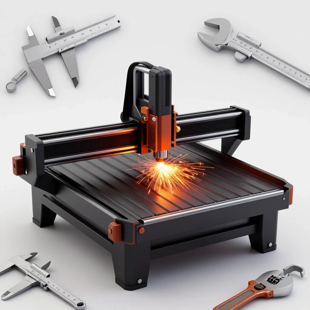
The jump to a CNC plasma table setup is often the biggest turning point for a micro-manufacturer. It moves you from “hand-cutting” to “manufacturing.” However, it is not a “plug and play” solution. I spent weeks leveling my gantry and squaring the rails. If the table isn’t perfectly level, your torch height control (THC) will struggle, leading to poor cut quality and wasted material.
Stepper vs. Servo Motors in CNC Systems
Stepper motors move in fixed increments or “steps,” while servo motors use a closed-loop system with encoders to constantly monitor and correct their position. Servos are generally faster and more precise but come at a higher cost.
When I chose my first table, I went with high-torque steppers because they were cost-effective and reliable for the type of decorative and structural work I was doing. However, as I moved into higher-precision parts, I saw the value of servos. Servos won’t “lose their place” if the torch hits a tip-up. If you are scaling a fabrication shop and plan on running long, complex programs, the reliability of a closed-loop servo system is often worth the investment.
- Leveling: Use a precision machinist’s level on the rails, not just a carpenter’s level.
- Grounding: CNC plasma systems generate massive amounts of electrical noise. Use a dedicated ground rod for the table.
- Maintenance: Wipe down rails daily and check belt tension weekly to avoid “chatter” in your cuts.
Workflow Optimization Tips for CAD/CAM Handoff
CAD/CAM handoff is the transition from the design phase (Computer-Aided Design) to the manufacturing phase (Computer-Aided Manufacturing). Optimizing this transition involves creating clean files that the CNC software can interpret without errors.
I used to waste hours “cleaning up” drawings because of overlapping lines or open loops. Now, I follow a strict protocol for every part I design. I use layers to separate cut paths from etchings, and I always check for “double lines” before exporting my DXF files. This discipline has reduced my setup time by 30%. In an advanced shop, time spent at the computer should be minimized so time spent at the machine can be maximized.
- Establish a standard naming convention for all files.
- Create a library of “proven” cut settings for different material thicknesses.
- Use nesting software to maximize sheet yield and reduce scrap.
Creating Repeatable Assembly Protocols for Custom Builds
Repeatable assembly protocols are standardized sets of instructions and checks used to ensure that even one-off custom projects are built with consistent quality and accuracy. These guides help bridge the gap between a unique design and a professional finished product.
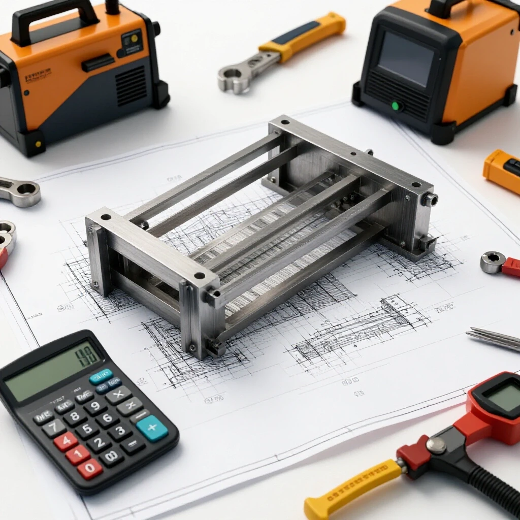
In custom fabrication, every job is different, but the way you build should be the same. I developed a system of modular assembly steps that I apply to every project. This prevents the “I forgot to weld the inside corner” syndrome that happens when you’re rushing. These protocols are essentially a roadmap for the build, ensuring that squareness, weld penetration, and safety are checked at every stage.
The Importance of Sequential Checkpoints
Sequential checkpoints are specific stages in the assembly process where work must be paused to verify accuracy before proceeding. This “stop and check” method prevents small errors from compounding into major structural failures.
I divide my builds into three phases: Fit-up, Tacking, and Final Welding. At the end of the Fit-up phase, I use a “Check” protocol. Is the frame square within 1/16th of an inch? Are the gaps consistent for the weld process I’m using? Only after these questions are answered do I move to tacking. This prevents the frustration of having to cut apart a fully welded structure because a base plate was 2 degrees out of alignment.
- Step 1: Material Verification. Ensure all pieces are cut to length and deburred.
- Step 2: Sub-Assembly Fit. Assemble smaller components before adding them to the main frame.
- Step 3: Squareness Check. Use 3-4-5 triangles or precision squares on all critical joints.
- Step 4: Weld Sequence. Plan the welding order to minimize heat distortion and warping.
Building Modularity into Custom Instructions
Modularity in assembly means breaking a complex project down into smaller, manageable units that can be worked on independently. This approach makes it easier to manage space and allows multiple people to work on different parts of a project simultaneously.
Even for a unique, one-off build, I look for “repeating modules.” If I am building a large industrial mezzanine, I treat each railing section as a module. I create a simple jig for that module, which ensures every section is identical without having to remeasure every single time. This use of jigs and fixtures is a core workflow optimization tip that separates the pros from the hobbyists.
- Identify repeating shapes or sub-assemblies in the design.
- Create a temporary “jig” on your fabrication table using clamps and stops.
- Document the assembly order for that specific module to ensure consistency.
Measuring Success and Tracking Metrics
Tracking metrics involves recording data on shop performance, such as machine uptime, material waste, and labor hours per project. This data allows you to make informed decisions about future upgrades and process changes.
You cannot improve what you do not measure. I keep a simple spreadsheet that tracks my “Project Velocity.” I record how many hours I estimated versus how many hours the build actually took. If a project goes over, I look for the bottleneck. Was it a layout issue? Did the 3-phase converter trip? Was the assembly guide unclear? Over time, these metrics have allowed me to price my work more accurately and identify where my shop needs the next upgrade.
Capital Amortization and Maintenance Intervals
Capital amortization is the process of spreading the cost of an expensive tool over its useful life. Maintenance intervals are the scheduled times when equipment must be serviced to prevent breakdowns.
When I bought my CNC plasma table, I didn’t just look at the purchase price. I looked at the “cost per hour” over a five-year lifespan. This helped me realize that spending more on a robust gantry would save me money in the long run by reducing downtime. Similarly, I have a strict maintenance calendar. Every Monday morning, I spend 30 minutes greasing bearings, checking air filters, and cleaning torch consumables. This small investment prevents the “emergency” repairs that always seem to happen during the busiest week of the month.
- Track “consumable life” (nozzles, electrodes) to predict operating costs.
- Log all machine downtime to identify patterns of failure.
- Review your shop layout annually to see if material flow can be further optimized.
As you move forward, remember that the goal of these systems is to give you more control over your craft. Transitioning to a semi-professional space is a marathon, not a sprint. By focusing on a solid advanced workshop layout, reliable power, and clear assembly protocols, you are building a foundation that can support your growth for the next 20 years.
Frequently Asked Questions
How much space do I really need for a CNC plasma table? While the table itself might be 4×4 or 4×8, you need at least 3 feet of clearance on all sides for maintenance and loading. Ideally, you should have enough room to swing a full sheet of steel into place without hitting other machinery. Total footprint for a 4×8 table is usually closer to 10×14 feet.
Can I run a 3-phase welder on a rotary phase converter? Yes, but you must ensure the converter is sized correctly. Welders have high “inrush” current when the arc starts. A general rule is to size your RPC at least double the horsepower or KVA rating of the welder to handle the surge and maintain voltage balance.
What is the best way to handle grinding dust in a small shop? Source capture is king. Use a “downdraft” table or a high-velocity vacuum attachment on your grinders. For general air cleaning, a ceiling-mounted air scrubber with a HEPA filter will help catch the fine particles that the vacuum misses.
How do I know if my shop floor can handle a heavy ironworker? Check the thickness of your concrete. A standard 4-inch slab is usually sufficient for machines up to 5,000 lbs if the weight is distributed. For heavier, vibrating machinery, you may need to cut out a section of the floor and pour a thickened “isolated” pad.
Why is my CNC plasma cut quality inconsistent? The most common culprits are poor grounding, moisture in the air lines, or a table that isn’t level. Ensure your air is “instrument dry” using a refrigerated dryer or a multi-stage desiccant system, and verify your table is square and level within 1/32nd of an inch.
Do I need an engineer to design my dust collection system? For most micro-manufacturers, you can design it yourself using CFM and static pressure calculators available online. The key is to keep duct runs short, use smooth-walled pipe, and avoid sharp 90-degree turns which kill airflow velocity.
What is the “3-4-5 rule” in metal assembly? It is a way to ensure a corner is perfectly square (90 degrees). If one side is 3 units long and the other is 4 units long, the diagonal between them must be exactly 5 units. This is a vital check in any repeatable assembly protocol.
How often should I balance the legs on my phase converter? You should check the voltage balance whenever you add a new machine to the circuit. Ideally, you want the voltage between all three legs to be within 2-3% of each other while the machines are running to prevent motor overheating.
(This article was written by one of our staff writers, Edward Sinclair. Visit our Meet the Team page to learn more about the author and their expertise.)