How to Calculate Precise Fit-Up for Welded Joints (Guide)
In my fourteen years on the shop floor, I have learned that a weld is only as strong as the preparation that precedes it. I remember early in my career, I was tasked with fabricating a heavy-duty equipment rack for a local warehouse. I was confident in my bead consistency, but I rushed the alignment phase. I didn’t account for the way heat pulls metal during the cooling process. When the rack was loaded to its rated capacity, the bottom rail buckled. It wasn’t the weld that snapped; it was the joint itself that failed because the fit-up was sloppy, leaving a hidden void where fusion was incomplete. That day taught me that structural integrity starts with a ruler and a square, not just a torch.
For the risk-averse fabricator, the goal is to eliminate variables. We want to know exactly how a joint will react when the heat is applied and how it will perform under a load. This requires a deep dive into the physics of the metal, the geometry of the connection, and the safety protocols that keep our workshops running without incident.
Understanding Structural Metal Load Capacity and Material Stress
Structural metal load capacity is the maximum amount of weight or force a specific piece of steel can support before it deforms or breaks. This is often measured in pounds per square inch (PSI) or Megapascals (MPa). Understanding these limits allows a fabricator to choose the right material thickness and joint design for the intended task.
When we talk about material stress, we are looking at how internal forces are distributed within the metal. In a garage fabrication safety context, you must respect the yield strength of your material. Yield strength is the point where the metal will no longer return to its original shape after being bent. For common A36 structural steel, this is typically around 36,000 PSI. If your joint preparation is poor, you create “stress risers”—tiny areas where the load concentrates. These spots are where cracks begin, often leading to a catastrophic failure of the entire assembly.
Before you even turn on your welder, you should look at the safety margins. In my shop, I never design for the exact weight a project will hold. I use a safety factor, usually 2:1 for static loads and 4:1 for dynamic loads (things that move or vibrate). This means if a bench needs to hold 500 pounds, I design it to hold 1,000. This buffer accounts for minor inconsistencies in material quality or slight deviations in your joint alignment.
| Material Type | Yield Strength (PSI) | Common Use Case | Weldability Rating |
|---|---|---|---|
| A36 Mild Steel | 36,000 | General Frames, Brackets | Excellent |
| 1018 Cold Rolled | 54,000 | Precision Parts, Shafts | Good |
| 6061-T6 Aluminum | 40,000 | Lightweight Structures | Moderate |
| 304 Stainless Steel | 30,000 | Corrosion Resistance | Good (High Heat Sensitivity) |
The Impact of the Heat Affected Zone Weakness
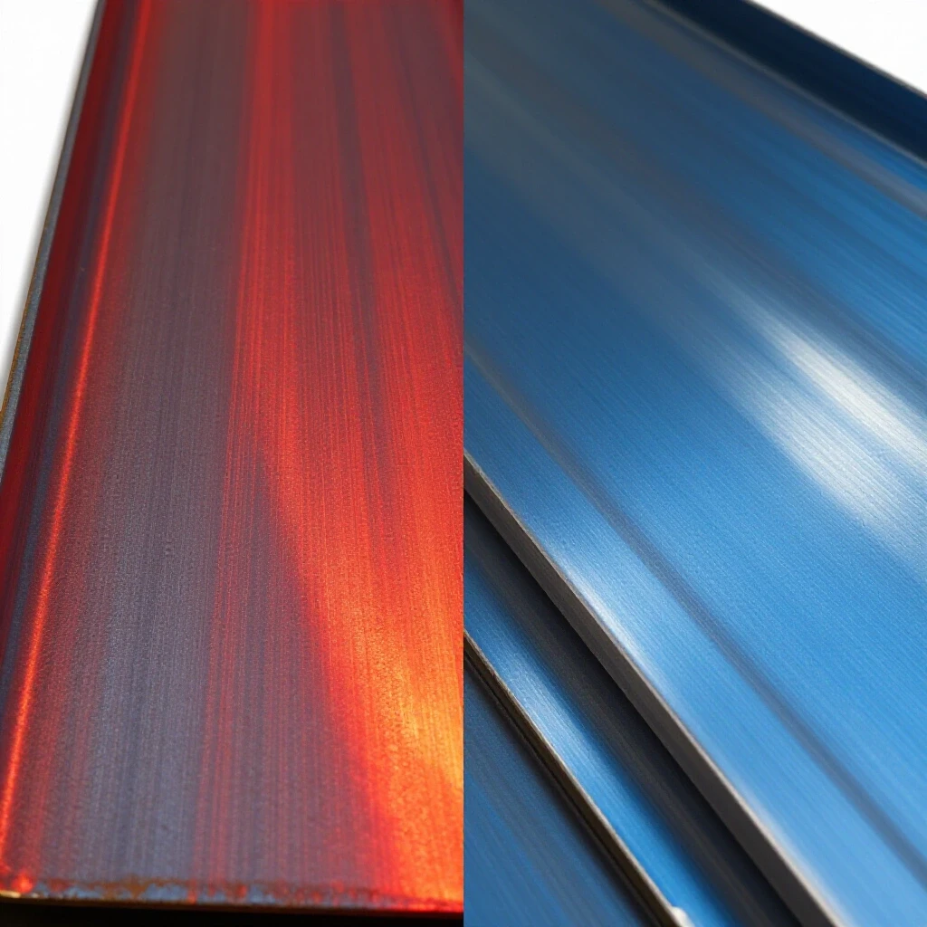
The Heat Affected Zone (HAZ) is the area of base metal surrounding the weld that has not melted but has had its microstructure altered by the intense heat. This zone is often the weakest point of a completed fabrication because the heat can make the metal more brittle or reduce its original strength. Understanding the HAZ is vital for ensuring the longevity of your project.
When you prepare a joint, you are essentially managing how much heat you need to put into the metal to get a good bond. If your parts don’t fit together tightly, you have to use more filler metal and more heat to bridge the gap. This expands the HAZ. A larger HAZ means more area for potential “brittle fracture,” where the metal snaps like glass instead of bending.
In my experience, many intermediate fabricators ignore the HAZ because it isn’t visible to the naked eye. However, if you’ve ever seen a weld pull a chunk of the base metal right out of the frame, you’ve seen a failure in the HAZ. By calculating a precise fit with minimal gaps, you can use lower amperage and faster travel speeds, which keeps the HAZ as small as possible. This preserves the structural metal load capacity of your base material.
Calculating Geometry for Structural Integrity
Joint geometry involves the specific angles and distances between two pieces of metal intended for joining. This includes the bevel angle, the root face, and the root opening. Proper geometry ensures that the weld penetrates through the entire thickness of the material rather than just sitting on the surface.
For materials thicker than 3/16 of an inch, a simple square butt joint is rarely enough. You need to create a “V” or “U” shape to allow the electrode to reach the bottom of the joint. I typically use a 30 to 37.5-degree bevel on each side, creating a total included angle of 60 to 75 degrees. This provides enough space for the slag to escape (if using flux-core or stick) and for the gas to shield the puddle effectively.
The “root face” is the flat part at the bottom of your bevel. If this is too thin, the heat will blow a hole right through it (burn-through). If it is too thick, the weld won’t penetrate to the other side. I find that a root face of about 1/16 to 3/32 of an inch works best for most structural projects. Getting these measurements right is the difference between a joint that looks good on the outside and one that is actually solid all the way through.
- Bevel Angle: The angle at which the edge of the metal is ground.
- Root Opening: The gap between the two pieces at the bottom.
- Root Face: The un-beveled portion of the edge.
- Included Angle: The total angle of the V-groove (sum of both bevels).
Establishing the Ideal Root Gap Spacing
The root gap is the physical distance between the two pieces of metal at the base of the joint. This gap is necessary to allow the weld metal to flow through the joint and fuse the bottom edges together. Without a proper gap, you risk “lack of fusion,” where the two pieces are only joined at the top.
According to AWS (American Welding Society) standards, a common root gap for structural steel is between 1/16 and 1/8 of an inch (roughly 1.5mm to 3mm). If the gap is too narrow, the weld won’t penetrate. If it is too wide, the puddle will fall through, and you will struggle to bridge the distance, leading to excessive distortion. I use dedicated spacers or even a specific diameter of welding rod with the flux knocked off to ensure my gap is consistent from one end of the joint to the other.
Consistency is the key here. If your gap starts at 1/16 and grows to 1/4 of an inch by the end of the seam, your heat settings will be wrong for half of the weld. This is a common point of frustration for makers. They think their welder is acting up, but the reality is that the inconsistent gap is changing the way the metal absorbs the heat.
Preventing Distortion with Tack Welds and Fixturing
Distortion is the warping or twisting of metal caused by the uneven heating and cooling during the welding process. As the liquid metal in the weld puddle cools, it shrinks, pulling the surrounding base metal with it. Without proper fixturing, a perfectly square frame can quickly turn into a trapezoid.
To combat this, I rely heavily on tack welds. These are small, temporary welds that hold the parts in alignment while the main beads are laid down. For a standard structural joint, I place tacks every 2 to 4 inches. I also use “bridge tacks” if I need to maintain a specific root gap under heavy heat. These are tacks that jump across the gap without filling it, acting like tiny structural braces.
Fixturing is another essential tool. I use heavy steel tables, C-clamps, and magnetic squares to lock everything in place. However, you must be careful. If you clamp a part too tightly, the internal stresses have nowhere to go, which can lead to cracking in the weld as it cools. The goal is to hold the alignment while allowing the metal to “breathe” slightly. It is a delicate balance that comes with practice and careful observation.
- Clean the surfaces: Remove all mill scale, rust, and oil.
- Align the parts: Use squares and levels to find the “true” position.
- Set the gap: Insert spacers to maintain the 1/16 to 1/8 inch distance.
- Tack from the center out: This helps distribute the heat evenly.
- Check for squareness: Always re-measure after your tacks are set.
Workshop Safety Checklist for Joint Preparation
Workshop safety is the practice of identifying and mitigating risks in the fabrication environment to prevent injury or equipment damage. This includes personal protective equipment (PPE), proper ventilation, and fire prevention. A clean and organized shop is a safe shop, and safety starts before the first spark flies.
When preparing joints, you are often using grinders and saws. These tools create high-speed debris and significant noise. I always wear a full-face shield over my safety glasses when grinding, as a shattered grinding disk is a real and present danger. Additionally, the dust from grinding certain metals can be toxic. I keep a high-quality respirator in my kit for any heavy grinding sessions.
Fire safety is another major concern. Grinding sparks can travel up to 30 feet and can smolder in a pile of sawdust or a greasy rag for hours before igniting. I maintain a “fire watch” for 30 minutes after I finish any hot work. This means I stay in the shop, cleaning up and checking for any signs of smoke or heat. It’s a simple habit that has saved many a garage from a late-night disaster.
- PPE Shade Ratings: Use Shade 10-13 for most arc welding; Shade 5 for oxy-fuel cutting.
- Ventilation: Ensure at least 2,000 cubic feet of air movement per minute in small shops.
- Fire Extinguisher: Keep a Class ABC extinguisher within 10 feet of your welding station.
- Gas Flow Rate: Set your shielding gas (like 75/25 Argon/CO2) to 15-20 CFH (cubic feet per hour).
Troubleshooting Common Welding Defects in Fit-Up
Welding defect troubleshooting is the process of identifying flaws in a weld bead and tracing them back to their root cause, which is often found in the joint preparation. Common defects include porosity, undercut, and slag inclusions. By identifying these early, you can adjust your fit-up technique to prevent them in the future.
Porosity looks like tiny holes or bubbles in the weld, similar to a sponge. This is often caused by a welding gas flow rate that is too low or by wind blowing the gas away. However, it can also be caused by “trapped” air in a poorly fit joint. If the gap is too tight and there is moisture or oil inside, the heat turns that liquid into gas, which then gets trapped in the cooling metal.
Undercut is a groove melted into the base metal next to the weld toe that isn’t filled by the weld metal. This is a major structural red flag because it thins the base metal and creates a sharp corner where cracks can start. While often a technique issue, undercut can also happen if your bevel angle is too steep, making it hard to get the filler metal to “wash” into the sides of the joint.
| Defect | Visual Appearance | Likely Root Cause | Fix |
|---|---|---|---|
| Porosity | Small holes/pits | Dirty metal or low gas flow | Clean to bare metal; check CFH |
| Undercut | Grooves at weld edges | Too much heat or bad angle | Lower amperage; adjust bevel |
| Lack of Fusion | Gap between weld and base | Gap too tight or travel too fast | Increase root gap; slow down |
| Burn-through | Hole in the metal | Root face too thin or too much heat | Increase root face thickness |
Real-World Case Study: The Utility Trailer Failure
A few years ago, a friend asked me to look at a utility trailer he had built in his garage. He was worried because he noticed a small crack forming near the tongue of the trailer. Upon inspection, it was clear that the crack started at a joint where two pieces of C-channel met.
The issue wasn’t the quality of his welding beads—they looked beautiful. The problem was the fit-up. He had ground the edges of the C-channel into a sharp point with no root face and pushed them tightly together with zero gap. Because there was no gap, the weld only penetrated about 20% of the metal’s thickness. On the outside, it looked like a solid 1/4-inch weld, but on the inside, the two pieces of steel were barely touching.
The vibration from driving down the road caused the “cold” part of the joint to rub together, eventually snapping the thin layer of weld metal that was holding it all together. We had to cut the tongue off, grind proper 30-degree bevels with a 3/32-inch root face, and leave a 1/8-inch gap. After re-welding with full penetration, that trailer has seen thousands of miles without a single issue. This serves as a reminder that what you can’t see inside the joint is just as important as what you can see on the outside.
Essential Tools for Precise Joint Verification
To achieve consistent results, you need a set of tools dedicated to measuring and verifying your joints before you strike an arc. These tools don’t have to be expensive, but they do need to be accurate. I keep a dedicated “prep kit” in my top drawer so I’m never tempted to eyeball a measurement.
A good set of feeler gauges or a “welding gap gauge” is indispensable. These allow you to check the root opening with precision. I also use a “hi-lo” gauge, which measures the internal alignment of two pieces of pipe or plate. If one side is higher than the other, the weld will be uneven, leading to stress concentrations.
Finally, never underestimate the power of a simple straightedge and a machinist’s square. Metal often comes from the mill with a slight bow or “camber.” If you don’t account for this during your fit-up, your entire project will be crooked before you even start. I spend about 30% of my project time just measuring and checking for squareness. It sounds tedious, but it saves hours of “cutting and re-doing” later on.
- Machinist’s Square: For verifying 90-degree alignments.
- Feeler Gauges: For measuring small root gaps (0.5mm to 5mm).
- Angle Finder: To ensure bevels are consistent (e.g., 30 or 37.5 degrees).
- Caliper: For measuring material thickness and root face depth.
- String Line: For checking long-distance alignment on frames.
Final Steps for a Structurally Sound Build
Once you have calculated your gaps, ground your bevels, and tacked your project together, there is one final step: the visual audit. I walk around the entire project with a flashlight. I look into the gaps to ensure there is no debris. I check the tacks to make sure they haven’t cracked. I verify that the heat hasn’t already pulled the project out of square.
This “slow down” period is vital for the risk-averse fabricator. It is the last chance to fix a mistake easily. Once you lay down a full-penetration bead, fixing an alignment error requires a grinder and a lot of sweat. By being methodical in your preparation, you are not just building a project; you are engineering a structure that you can trust.
Remember, welding is a science disguised as an art. The “art” is the steady hand and the pretty bead. The “science” is the geometry, the metallurgy, and the physics of the joint. Master the science of the fit-up, and the art will follow naturally.
FAQ: Common Questions on Joint Preparation and Fit-Up
How do I know if my root gap is too wide? If you find that you are constantly “blowing through” the metal or if the puddle is sagging and won’t bridge the gap, your opening is too wide. Generally, for DIY projects, any gap over 3/16 of an inch (about 5mm) becomes very difficult to manage without advanced techniques like using a backing bar.
Can I weld a joint that has a small amount of rust on it? You can, but you shouldn’t. Rust, mill scale, and oil introduce impurities into the weld puddle, leading to porosity and weakened structural integrity. For a structurally sound joint, always grind the metal until it is shiny and “white” at least one inch back from the weld zone.
What is the best way to maintain a consistent gap on a long seam? I recommend using “spacers.” You can use pieces of scrap sheet metal, copper shims, or even the shanks of drill bits. Place them every six inches, tack the joint, and then remove the spacers before you begin your final weld pass.
Why does my metal warp even when I use clamps? Clamps can only do so much. Metal expands when hot and shrinks when cool. If you weld a long seam all at once, the cumulative shrinkage will pull the metal. Try “stitch welding,” where you weld two inches, move to a different part of the project, and weld two inches there. This keeps the overall heat input lower.
Is a 60-degree included angle always necessary? It is a standard for a reason. It provides the best balance between access to the root and the amount of filler metal required. A narrower angle might be hard to penetrate, while a wider angle will cause more distortion because you are putting more molten metal into the joint.
How do I calculate the safety factor for a workbench? Take the maximum weight you expect the bench to ever hold (say, 400 lbs) and multiply it by your safety factor (2 for a static bench). You should design the joints and select material thicknesses that can theoretically support 800 lbs. This accounts for dynamic forces, like if you drop a heavy part onto the bench.
What happens if I don’t put a bevel on thick plate? If you weld 1/2-inch plate with no bevel, the weld will only penetrate maybe 1/8 of an inch deep. The middle of the plates will not be joined at all. Under a heavy load, the weld will simply peel off the surface of the metal, leading to a total failure.
What is the “root face” and why can’t I just grind the edge to a sharp point? A sharp point (a “knife edge”) has very little mass. When the welding arc hits it, it melts instantly, often leading to a large hole. A root face (a small flat landing) acts as a heat sink, allowing you to get full penetration without the metal falling away.
How does shielding gas flow rate affect my joint? If your flow rate is too low (under 10 CFH), the weld won’t be protected from oxygen, causing porosity. If it’s too high (over 30 CFH), it can actually create turbulence that pulls air into the puddle. Staying between 15-20 CFH is the “sweet spot” for most indoor workshop environments.
What is the most common mistake intermediate fabricators make? The most common mistake is over-welding. People think that “more weld is better,” but excessive weld metal creates more heat, more distortion, and a larger Heat Affected Zone. A correctly sized weld that achieves full penetration is always stronger than a massive, humped-up bead that only sits on the surface.
(This article was written by one of our staff writers, James Harlan. Visit our Meet the Team page to learn more about the author and their expertise.)